The PEDDIE Smallarms Corporation Ltd.
and their limited involvement in the selection process for the War Office 1906 Pattern Miniature Rifle
Plus the PEDDIE, PARKER, SUTHERLAND and other barrel tangent sights
Noted in the Proceedings of the Small Arms Committee at the time, John Taylor Peddie submitted a drawing, a rifle, and a probably ignored request for a financial consideration of the 'invention' should it have been accepted. If the Committee were aware of the fact that the design was effectively that of the Demay training rifle, a Lebel representation, they may well not have been overly impressed. Peddie wrote a letter to the War Office confirming the delivery of his 'new' rifle for assessment.
PEDDIE Small Arms Corporation, Ltd
Offices — 53, VICTORIA STREET, LONDON, S.W.
December lst. 1905.
In accordance with your letter and specification of Oct 25th our Mr. Peddie personally delivered a "Pedminster" Cadet Rifle this afternoon at the War Office which we think meets the suggestions contained in your specification with the following exceptions.
(1) That the pull of the rifle is not a drag pull, but this can easily be altered if desired.
(2) Owing to the shortness of time we were unable to make a satisfactory safety catch. but we subhmit the proposed pattern for your approval as per drawing attached herewith.
In all other respects we think the rifle fulfils requirements.
With references to clauses A, B, C and D of your letter of the 25th October would beg to reply as follows:-
(a). We accept unconditionally the terms laid down in the attached memorandiua for inventors but in the event of the rifle being adopted we desire compensation for the invention. The terms for which can be arranged mutually hereafter,
(b). The number of the British patent covering the Pedminster Cadet Rifle is as follows No. 21,636 19O5, filed 24-10-05
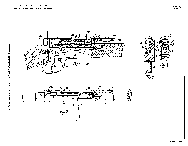
Below: the submitted drawing for the safty catch.

The Patent application is replicated below. It was made in the what appear to be the names of three Frenchmen, presumably French Canadians involved with Peddie in the design. However, at that time no patent was granted as, for some reason, the 'Sealing Fee' had not been paid.
Improvements in and connected with Rifles and other Small Arms.
Abstract
Patent application No. 21,636.
Demay, J. M., Ferreol, B., and Murigneux, J. M.
Sept. 25th 1905, [date applied for under Patents Act, 1901].
Breech actions, sliding breech-block. - Relates to improvements in rifles, particularly small - bore rifles for miniature ammunition. The front end of the bolt b is closed by a screwed plug g, having an orifice for the firing-pin f provided with a projection fitting into a recess of the plug. The hammer d is thrown forward to strike the firing-pin by a spring h bearing at its rear end against a collar i fixed in the bolt by a slot and screw. The cocking-piece l Fig. 6, is carried on a sleeve o fixed to the hammer by a screw pin p. The hammer is cocked, when the bolt is turned, by the part s of the cocking-piece engaging the camslot of the bolt b. The sear m and trigger n are carried on the end of a spring g. The extractor, shown separately in Fig. 11, consists of a rod w having a semicircular extractor y at its front end and connected to the bolt b by fitting a projection v into a transverse slot in the bolt. Normally, the complete withdrawal of the bolt and extractor is prevented by a stop z, which can be drawn aside against the action of the spring 2 by the thumb-piece 3. Trigger - guards. - The trigger-guard plate is attached by a fork 6 at its forward end fitting over a pin 7, and a screw 8 at its rear end.
In the event, the S.A.C. Committee awarded the Peddie company a license to manufacture the eventually selected rifle, an option that Peddie evidently did not take up, as only the Birmingham Small Arms Co. and the London Small Arms Company went into production.
Comprehensive detail of the Peddie submission and involvement can be found in the facsimiles of the S.A.C. proceedings that can be viewed from the links below. Much of the correspondence between the involved submitting companies and the committee members responsible for design and production matters is included.
These are searchable up to a point, as the scans are not all perfect. Try entering "Peddie". There are some references in tranches, 1, 5 and 6, but most related material is in tranche 4.
The optical character recognition is not able to cope entirely successfully with the various layouts, and a considerable number of reports are in long-hand. However, the material is almost entirely legible, presents a remarkable history of the conception of the rifle, and affords a research opportunity otherwise not available to those remote from the original archives.
The first tranche is shown here, and the remaining five are on separate pages accessible from the follow-on links.
Proceedings of the Miniature Rifle Committee 1905-06
TRANCHE 1 of 6
This in the form of a large searchable PDF document, which may take a few moments to display.
Please be patient - if the subject interests you it will be worthwhile.
Double tap tablet or click ![]() for full page display.
for full page display.
Proceedings of the Miniature Rifle Committee 1905-06 ~ Tranche 2 of 6
Proceedings of the Miniature Rifle Committee 1905-06 ~ Tranche 3 of 6
Proceedings of the Miniature Rifle Committee 1905-06 ~ Tranche 4 of 6
Proceedings of the Miniature Rifle Committee 1905-06 ~ Tranche 5 of 6
Proceedings of the Miniature Rifle Committee 1905-06 ~ Tranche 6 of 6
Go to the Main Page for the: War Office 1906 Pattern Miniature Rifle
The PEDDIE, PARKER, SUTHERLAND and other contemporary barrel tangent sights between 1902 and 1920
J.T. Peddie was the designer of the well-known "Peddie" barrel-mounted folding tangent-leaf rear-sight used mainly for target shooting with the "Long" Lee-Enfield or Lee-Metford rifles.
Peddie's design work for his most well-known sight, and that of the equivalent Sutherland model, probably commenced early in the 20th. Century. Each designer first made patent applications in 1902 for barrel-mounted tangent leaf sights that had their elevation adjustments for short range made on an inclined ramp, and those for long range using the slider with the leaf in the vertical position. There was nothing particularly new in this, as the configuration had been employed for decades, but their designs added sophistication in fineness and ease of adjustment, along with correction for windage, vernier scale, and an early orthoptic aperture option added to the customary "V" or "U" notch.
John Taylor Peddie was born in 1879 and died in England shortly after the Second World War in 1947. In the late Nineteenth Century he was employed by a Canadian sight manufacturing company, and patents are to be found that were applied for in Montreal.
By 1903, Peddie had left North America for England, where he was employed by the Vickers Sewing Machine Company, eventually in management. This is, of course, the reason that Peddie's rear-sight was manufactured by that company. But Vickers were, in a few short years, to be heavily involved with the production of war matériel, and such items as volunteer target sights later went very much by the board.
Shortly after his arrival in Great Britain, Peddie set up the Peddie Small Arms Corporation Ltd., but, for reasons not entirely clear, although very possibly to do with the personal expense of his intended own manufacture of his designs, during 1906 he sold the company to the Birmingham Small Arms Company.
As well as being an engineer, and authoring "First Principles of Production : a Study of the First Principles of Production and the Relation of Science to Industry." published by Longmans (1915), Peddie was also something of a philanthropist, and wrote a number of highly academic tomes such as ; "On the relation of imports to exports; a study of the basis of a new national and imperial policy" (1916); "A national system of economics; with a consideration of the Paris economic resolutions and of their influence on nationality" (1916); "Economic reconstruction; a further development of a national system of economics" (1918); "The Invariable Standard and Measure of Value" (1928); "The dual system of stabilisation" published by MacMillan (1930); "The economic mechanism of Scripture : the cure for the world crises" - MacMillan (1934); "The Rule of Equity : the Correct Approach to World Peace" Published in London by Williams And Norgate (1940); and the much earlier and rather more here relevant book entitled "British industry and the war" (1914). At least four of these books have been considered worthy and timeless enough to be reprinted, and are usually currently available.
One Italian Captain Calichiopulo had patented an aperture arrangement in 1902, and this quite possibly led to Peddie's adaptation of an aperture in a modified elevation slide. Indeed, a sight was later produced in their joint names; the Peddie-Calichiopulo model of 1909. The sight was 'reviewed' in a particularly prescient article in an issue of the "Engineer" journal that year. The value and potential of the aperture sight for the military was certainly not lost on the author; along with the tubular fore-sight, which foretold of the current globe and ring element target fore-sights of today; although it may not have been at its best for low-light military operations in the field.
We here replicate that fascinating and comprehensive article from the "Engineer".
S I G H T S FOR S M A L L A R M S A N D M A C H I N E - G U N S
As so much enterprise is being devoted to the improvement of aiming media, and more especially to that applicable to military small arms, it may not be in.appropriate to discuss the technicalities involved in aiming in connection with a new sighting system invented by Captain Antonio Calichiopulo, R.A., Italian Army, with developments by Mr. J. Taylor Peddie, late Lieutenant, London Rifle Brigade, and now in process of adaptation for military service by Messrs. Vickers Sons and Maxim, Limited. Of this now system illustrations are given on page 752.
It is hardly yet sufficiently appreciated that enhanced range and precision require concurrent development of the sights which are the actual media through which the rifle's precision is utilised, and also that all such improvements in rifle advancement in the intelligence of the soldier. It has not apparently impressed itself in military circles that man and rifle are one unit, of which the two aspects—i.e., man and rifle — are of equal importance. From the standpoint of the expert it is too much to expect that crude notches and points, which served but indifferently for the aiming of the inaccurate muskets of antiquity, could, with the addition of almost equally crude adjusting mechanism, prove an efficient medium for directing rifles of extreme precision, capable of attaining possibly ten times the range. Yet such .are the sights which military critics are defending, mainly upon the ground that the exigencies of service preclude the use of refinements.
It is not, however, our present purpose to discuss the practicability or otherwise of improved sights, but rather to treat of the technics of aiming and the method by which the vertical and lateral angular relation of the barrel to the line of sight, necessitated by gravity and wind, are determined and maintained. Aiming media have two distinct functions : the first , to enable the establishment of exact coincidence with the line of sight, a function performed by the eye with the aid of notches, apertures, points, and such like, which constitute the sights proper ; and the second, to exactly determine the angles before referred to. The angle measuring mechanism is attached to the back-sight, and allows of fine adjustment of the rifle in angular relation with the line of sight. It is commonly, but, nevertheless, erroneously, supposed that the
required trajectory is attained by giving elevation to the barrel in relation to the plane of the horizon, whereas, in fact, the breech end of the rifle is depressed with the fore-sight as a pivot in angular relation with an imaginary line proceeding from the objective to the firer's eye, and called the line of sight; it would, therefore, be more correct to speak of adjusting the rifle than of adjusting the sight, the Latter being the fixed quantity. The sights proper are optic.al instruments, the design of which is more within the province of the optician than either the gun-maker or soldier ; the adjusting mechanism, on the other hand, comes within the domain of the engineer, or scientific-instrument maker, and the combination, when fully developed, may be appropriately passed to the gun-maker for adaptation to the particular requirements of the weapon. The optician has been so much accustomed to employ the use of glass in aid of the eye that he has been led to overlook the possibilities of metal alone in the construction of aiming media complying with physical requirements of the human eye, from which Nature permits no departure. The difficulties introduced by lenses, quite apart from their natural fragility, are such as to more than counteract their virtues, except for very specialised uses, but the aid of optical science has of late been sought in designing metal sights in compliance, as far as may be, with the physical characteristics of the eyes with which they are employed.
That the problem of reconciling technical, optical, and military considerations is by no means insurmountable has already been abundantly demonstrated at Bisley by numerous marksmen with some of the excellent sights which were evolved in response to the invitation of the National Rifle Association [Ed: of Great Britain]. The most marked improvement in the shooting which immediately followed was in each case associated with the use of a small aperture or peephole mounted near the eye as a back-sight in conjunction with screw-operated mechanism for vertical and lateral adjustments. Although the National Rifle Association regulations did not permit of any alteration of the fore-sight, the improvement in shooting as indicated by the scores made, has, in the last few months, exceeded that of all previous time, and as the substitution of a peephole for a V-notch has been the only material alteration made, these beneficial results must be attributed solely to the optical virtues of the aperture.

The underlying principle of Captain Calichiopulo's invention, as shown in the elevation of the gun. Fig. 1, and in the perspective view, Fig. 5,

is to establish coincidence with the line of sight by means of two apertures, the back-sight (Figs. 2 and 3) carrying the adjusting mechanism,

the fore-sight (Figs. 4 and 6) being of a tubular shape, having external walls bearing a predetermined definite relation in size to the back-sight aperture, the size of which is in turn determined by its distance from the eye and the fore-sight.
 ....
.... 
The proper correlation of dimensions and distance gives a view of the objective surrounded by an annular ring of light in an unobstructed field and with full natural illumination. Exact coincidence of the fore-sight with the line of sight exists when the objective is centred in the field (Fig. 7);

while the slightest movement of the back-sight, or attempt to get out of alignment, is at once apparent by the annular ring of light becoming a crescent, or some one of a variety of shapes other than circular.
The back-sight aperture, with suitable adjusting mechanism, may be attached to either the barrel or small of the stock. Technical considerations indicate the latter as the correct position, whilst military opinion favours the former. In this it is influenced by the possibility of injury to the face by a blow from the sight, impelled by the recoil, when, under stress of rapid firing, the rifle is not held as securely as might be.
The adjusting mechanism, upon which the back-sight is mounted, known as the Peddie system, as shown well in the perspective view. Fig. 5, is screw-operated for elevation and lateral motion. The moving member of the elevation scale is divided so as to give a vernier reading to single minutes of angle, and on the opposite side figures are impressed indicating yards of range. The definite proportions sustained by the lengths of minutes of arc at all distances affords a convenient basis for sight adjustments, and incidentally a simple means of calculating the trajectory of the projectile. The internal diameter of the tubular fore-sight may be as much as 6 millimetres, but in practice 4 millimetres has been found to give a field of ample dimensions, into which no difficulty exists in centering the objective. The external diameter of the tube is proportionate to the diameter of the back-sight aperture, and in all cases permits of the use of sufficient metal to ensure the strength necessary for military services.
With the advent of automatic rifles, the Peddie-Calichiopulo sights will prove invaluable. The frequently-recurring recoil of the rifle is of a certainty bound to disturb the aim if a crude notch and point be used, necessitating a stoppage of fire for the purpose of realigning the rifle. The new system will overcome this difficulty, because the full strength of the eye is given to the objective, which can be continuously retained in view ; and if the rifle has a tendency to displace itself from its true position whilst fire is proceeding, it can be observed and checked. To those who study problems of this sort the practical nature and possible application of the new system will be apparent. It becomes manifest, therefore, that it will become a permanent feature in rifle mechanics, and that the old form of notches and point will disappear.
As will have been seen above, the sight was also intended for use with machine guns.
As a matter of interest, a Small Arms Committee proceedings memorandum of 1910
mentions the sight in Minute No 1133 II, of 7th. April.
"Small Arms Committee (1910) ‘103. Sights II. *Peddie-Calichiopulo Aperture Sights for Rifles. Proposed by Messrs. Vickers, Sons & Maxim Ltd.’, Proceedings of the Small Arms Committee, 7 April 1910, Minute No. 1133 II. "
"When first introduced for trial, the Vickers was fitted with a Peddie-Calichiopulo aperture sight that had been developed by Vickers, Sons & Maxim Ltd. for their commercial Class C gun. It was also trialled, unsuccessfully, for use on rifles."
Five years later a new model was introduced
General Routine Order 1005 dated 13 July 1915
Machine Guns – Battle Sights
Approval is given for the issue of Battle sights for .303-inch Maxim guns and .303-inch Vickers guns to cavalry regiments and Infantry battalions on a scale of one per gun.These sights are not interchangeable between the Vickers and Maxim guns and it must be stated on indents for which type of gun they are required.Indents should be sent to Ordnance Officers concerned, and issue will be made as supplies become available."
Antonio Calichiopulo lived in LaGrange, Turin, Italy, and on 1st. January 1909 he applied for a further patent associated with his orthoptic arrangement.
Improvements in and relating to Sighting Devices.
Abstract
19,536. Calichiopulo, A. Dec. 5, 1908. [Convention date]. Sighting-devices. - A sighting - device, more particularly applicable to fire-arms, comprises a circular opening in a tubular piece e forming the fore-sight, the periphery of this piece being designed to leave only a thin annulus of light between itself and the inner periphery of the back-sight when the two are in exact adjustment. The Specification as open to inspection under Section 91 (3) (a) comprises also sights of other shapes than circular, and provided with means for centring the object in the sighting-aperture. This subject-matter does not appear in the Specification as accepted.
Evidently an inveterate inventor, in 1911-12 Calichiopulo also patented a device for stereo photography.
_________________________________________
Only with the prototyping and trialling of the Lee-Enfield No.1 Mk.V rifle was the follow-on system of a rear-mounted aperture battle sight adopted for the British Forces, with the Enfield designed Pattern 1913 rifle following in its footsteps, of course leading to the Enfield Rifle No.3 (Pattern '14), the Lee-Enfield No.1 Mk.VI and the Lee-Enfield No.4 rifles. But these move rather further ahead than the times in which the barrel tangent sight still held sway, in the period when the 'Long'Lee-Metford and Lee-Enfield rifles were still important in volunteer competition target shooting, and whilst the 'new' Rifle, Short, Magazine Lee-Enfield was being introduced into service still with its barrel-mounted non-windage adjustable leaf sight, and the Canadian Ross Rifle was shortly to come into its own.
Not only did Peddie co-operate with Calichipulo, but with others too. At some point he came to some manner of agreement with Alfred G. Parker. Alfred snr.'s son, Alfred J. Parker was already working with his father's firm early in the first decade of the 20th. Century, and by 1910 he had become instrumental in the design and production of the company's sighting accessories. However, there is nothing yet discovered to indicate that either Alfred had any involvement in the design of the Peddie sight. Alfred Jnr. served in and survived the First World War, and set up his own equivalent business in 1928. A.T.C. (Arthur) Hale had joined Alfred Snr. prior to 1910 leading to the later adjustment of the company name to Parker-Hale.
With the passing of the first decade of the Twentieth Century conflict looked increasingly likely. Even the A.G. Parker company turned its manufacturing prowess to those of their products most needed by the military and recruit training; their conversion of obsolete service rifles into small-bore training rifles being a particular case in point.
Veering a little from this page's subject for just a single paragraph may illustrate the point.
Such rifles as the old Martini service rifles held in Government stores were converted by Parkers, WW.Greener and C.G. Bonehill for use by civilian clubs under the auspices of the Society of Miniature Rifle Clubs; and for incoming army recruits, such as the obsolescent 'Long" Lee rifles were adapted by Parkers to emulate the new Short Lee-Enfield in small calibres such as the ubiquitous .22 Long Rifle rimfire cartridge, and even some in the also obsolescent Morris centre-fire calibre of .297/.230-inch.
See: the Martini .22RF conversions;....the .22 Lee-Enfield RF Short rifle and the Lee-Enfield .22 No.1 Pattern '14 rifle.a
Returning to the tangent sights -
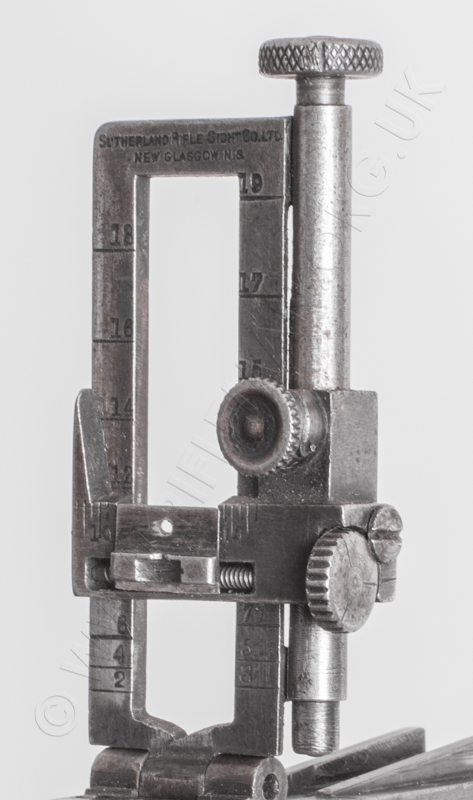
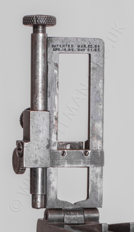
Patent details widely available include those applied for by Peddie and his associates, as well as those for the Sutherland Rifle Sight Company, of New Glasgow, Nova Scotia, whose designs were both contemporary and similar, and more than likely connected. There were many inventors climbing on this particula band-wagon, and several others are included for comparison or for their innovation - whether successful or otherwise!
Sutherland sights were often seen fitted to Ross service rifles as well as Lee-Enfields,
when competition rules allowed, the Ross being notably accurate as a target rifle.
It will be seen that, post the Great War (1914-1918), the marketing of such sights as these was practically non-existent. This limited the production years to little more that a decade and, with the current popularity of collecting old rifles on which they could be used for display or historic target-shooting competition, their rarity - certainly partly due to the usually expected natural losses over the ensuing years, has led to rarer models becoming extremely valuable; sometimes representing a significant proportion of the value of the rifle to which they are fitted. Loose original boxed examples can be at a particular premium.
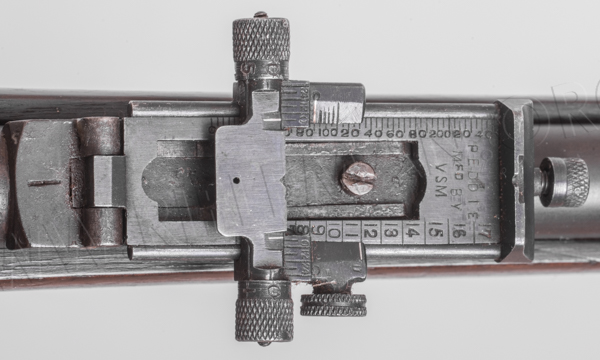
What was Alfred Parker's involvement with the Peddie sight? Perhaps nothing from a design point of view. A version of the Peddie sight was marketed, known as the "Peddie-Parker" model, and a boxed example carrying a Peddie-Parker label holds a sight with no hint of any Parker (A.G.P.) marking, nor even a patent no. that relates to a Parker product.

Our thanks go to the contributing reader for this image.
The sight, as all those we have seen, was clearly manufactured by the Vickers Sewing Machine Company and, along with the stamped initials "VSM", bears those patent numbers associated with Peddie's own applications. As perhaps the prime retailer of sights and sighting accessories, Alfred Parker was certainly an obvious person to approach as a good marketing prospect.
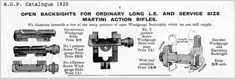
The company's catalogues were indeed annually posted out World-wide in huge numbers to gunsmiths and retailers everywhere, but there are few in evidence prior to 1920. By then, Parker's advertised mainly their rear-mounted folding aperture target sight designs for the various service rifles, meeting the NRA rules for the Service (b) class that permitted such accessories in competition. These were usually attached to the butt-socket with a suitable mounting plate, and hinged via the volley-sight 'dumbell' fulchrum. (See: Parker & Parker-Hale Service Sights)
Service(a) class still allowed only standard issue rifles with their barrel mounted tangent rear-sights, although commercially sold volunteer rifles could use either a windage adjustable replacement for the leaf's rear notch block, or a proprietary model such as that made by A.G.P. at their Bisley Works in Birmingham.

The earliest A.G. Parker Co. catalogue we have is 1920, and by then there was little mention of any tangent sights. Only the above commercial model remained available, although it was still possible to purchase complete standard issue barrel sights and spares for same. We have yet to see any contemporary advertising material for the Peddie-Parker model, although separate replacement slides were on offer, one with a vernier and aperture similar to that of the Peddie sight.
Below is a list of patents for tangent leaf sights between 1902 and 1911,
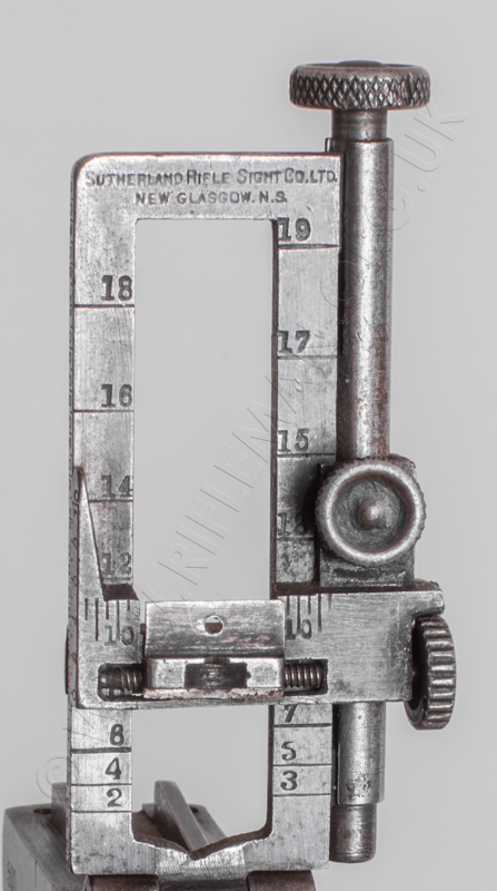
with close-up photographs of the Peddie and Sutherland models.
This affords a timeline for progress in the designs.
1614. Lodder, O. Jan. 21. 1902

Sights.—The back sight is arranged to have a lateral movement for wind adjustment. The sight base c slides in a dovetailed groove a in the sight bed, and is moved by an eccentric pin r, which slides in a groove s in the base c and is carried on a button m pivoted to the gun.
1959. Peddie, J.T. - Jan , 24th., 1902

Sights.—Fig. 2 shows the back sight in plan with the leaf raised and Fig. 4 shows it in vertical section with the leaf down. To enable the sight to be moved laterally for wind allowance, it is mounted upon a frame j, which is connected by dovetailed guides h, i to the gun, and is traversed by the screw l. The leaf m is retained in set position by the
spring k, which is graduated for short ranges. The lateral movement of the sight is indicated on the scale g.
20,269. Sutherland, M.E., Sept. 17. 1902
Sights.—The back-sight, shown in front and side elevation in Figs, 8 and 4, consists of a frame 27, shown separately in Fig. 6, having its upper ends connected by a block 37, shown separately in Fig. 7, and carrying a slide y which is operated by a screw 47. The connection between the screw 47 and slide 55 is effected by a nut on the screw,

which enters a recess in the slide and is locked therein by a screw 73. When a rough and rapid setting of the slide is desired, the screw 73 is released, and the slide is pushed into position and adjusted by the scale 84, but, when a fine setting is desired, the slide is moved into position by the screw 47 and is adjusted by the scales 85, 65. For wind adjustment the clip 86 is moved along the slide until the line 91 stands over the notch 58, and the setting is then effected by the scale 92. The block 37 is notched at 93, 95, to enable it to be used at the proper ranges.
23,419. Bansford, R. B. , [Peddie Rifle Sight Co.]. Oct. 27. 1902
Sights.—Relates to improvements upon the invention described in the Specification No. 1959 A.D. 1902. Fig. 1 shows the back-sight in perspective, and Fig. 2 shows it in plan to a larger scale. The slide r is locked to the leaf m by a device, shown enlarged in Fig. 5, consisting of a pawl x acted upon by a spring 5; and engaging with a rack y on the leaf. The springs may be replaced by a screw. The slide r is provided with a graduated arm v, to facilitate its adjustment on the leaf. The leaf is hinged to a plate j, which is connected by dovetails to the base, and is adjusted laterally by a screw l mounted in a boss s of the leaf.

866. Peddie, J. T. Jan. 16. 1905

Sights.—The bridge-piece of a lift-up leaf sight is made to swivel about its forward end for windage-allowance and can be locked in any position by a cam-roller. Fig. 2 is a plan of the bridge-piece carrying the ramp d and leaf e. Fig. 4 is a plan of the base a. The front end of the bridge-piece has a circular dovetailed bearing f which is fitted into the open-ended slot c in the base a. The rear end of the bridge-piece has a bearing g which fits into the arcuate dovetailed slot h in the base. The bridge-piece is locked in any desired position by a cam-roller k, shown separately in Fig. 6, placed in a transverse slot l of the base.
5237. Cremer, H. M. March 5,1906, [date applied for under Patents Act, 1901).

Sights.—Relates to back-sights provided with a pendulum, as described in Specification No. 2619, A.D. 1861, for indicating whether the sight is held vertically. The pivot 26 of the pendulum 27 is formed on the upper bar of the leaf-slide 21. The heel 16 of the leaf is formed with a shoulder 19 against which the end of the springs 17 abuts to steady the leaf. The leaf is mounted on a plate 11 having a notched rib 34 to enable the sight to be fixed to the spring plate 36 of the ' Stenman sight' shown in Fig. 6. The elevating-wedge 41 is withdrawn and replaced by the notched rib 34, which fits under the block 40 of the spring plate 36, as shown in Fig. 7.
5010. Marks, E. C. R., [Sutherland, M. E.]. March 1. 1907

Sights.—A protector for hack-sights consists of a part 1, which is fitted on to the sight by sliding, so that the inwardly-projecting flanges on its under side engage under the leaf of the sight, and of a part 4 which is hinged to the part 1 and is closed down on to the sight and heldby a spring catch 21. The protector is intended for sights of the kind described in Specification No. 5254, A.D. 1905, and the cover-piece 4 is formed with recesses to receive the projecting parts of the sight.
[Ed: Most of Marks' other contemporary patents involve shotgun and rifle actions, including gas-operated small-arms. Another application, No. 24,129 of 19th. April 1911 was for an adaptive sytem to fire blanks and miniature calibre ammunition from gas-operated weapons for practice and training. Another, No. 4992 of 31st. March 1915 is for a hyposcope to enable safe firing from trenches, See: Youlten's hyposcope and the Chandler Periscopic Trench rifle.
There was perhaps a 'training' philosopy attached to those then named Marks as, coincidentally, another Marks, initial H., was a joint applicant in April 1909, No. 8406, for an aiming rest for the .22 Martini rifle conversion. This was in conjunction with E.J.D. Newitt, and both H.Marks and Newitt were heavily involved with Lord Roberts in the setting up of shooting clubs and the Society of Miniature Rifle Clubs after the poor performance of British riflemen during the Boer Wars. ]

Sights. — Fig. 4 is an elevation of a leaf-sight provided with means for making fine adjustments for elevation and also for windage. The sight-bar is formed with a lug 26, Figs. 12 and 13, which is perforated to receive the sleeve 16 attached to the limb 8 of the leaf. The sight-bar can be slid to the approximate position required on the sleeve 16 and clamped by the set-screw 29. In order to make the fine adjustment, the sleeve 16 is raised or lowered by turning the head 58 of the screw 15, which is mounted on the leaf and engages with a screw-thread inside the sleeve 16. as shown in the section.

Fig. 13. The sight-bar consists of two parts 23. 24, Fig. 14, which are connected by screws 34. With in a recess 40 of the part 24 is mounted the windage-adjustment screw 41 having a milled head 43, Figs 4 and 15. The sight-block 35 is formed with a lug 56 in which the screw 41 works. A spring pin 49, Fig. 15, passes into and out of recesses 48 in the underside of the head 43, so that the turning of the head is indicated by a series of clicks. The screw 40 is kept in the sight-bar by the screw 60, which overlaps the head 43. Specification No. 20,269, A.D. 1902, is referred to.
Below: three close-up views of the Sutherland sight.
 >
>
 >
>
 >
>
5315. Gompertz, Xt. E. Campbell-. March 14. 1905

Sights and sighting-accessories. — In order to render it unnecessary to close one eye when taking aim, the fore-sight is hidden from one eye by a small plate or flap attached to the back-sight. Fig. 1 shows a flap d hinged to an extension c of the slide b. Fig. 4 shows a sight having the flap in two parts d1, d2, which are turned at right-angles to each other, as shown, for use at short ranges.
7244. Jones, H. Sefton-, [Sutherland, M. E.]. March 26. 1907
Sights.—Relates to wind-gauge leaf sights. (1) A peep-sight plate H, shown in detail in Figs. 7, 8, and 9, is mounted in a vertical dovetail groove e.
Figs. 5 and 6, in the laterally adjustable sight-plate F, so that when desired it can be raised into the position of the open sight b without affecting the adjustment of the wind gauge. Vertical movement of the peep-sight is limited by a projection f, Fig. 9, which engages a slot g formed in the bottom of the dovetail groove c, and the plate H is maintained in the raised position by a spring A, Fig. 8, which engages a recess j,To use the sight as a bar sight, the plate H is raised until its top is level with the top of the sight-plate F, where it is retained by the engagement of the spring h and a recess x, Fig. 8. (2) To provide means for judging the nature of the sight taken, the distance between the peep-hole d and the top of the plate H is made equal to the distance between the rays of light from the eye to the centre and outside of the circular hood K Fig. 12, of the fore-sight. If the sight taken is too coarse, a line of light can be seen between the top of the plate H and the inside of the top of the hood K. (3) A clicking indicator is provided on the elevating-screw E, consisting of a spring plunger m. Fig. 11, which engages a series of recesses q formed on the underside of the milled head of the screw. (4) To take up wear on the screw E, a compressed helical spring w, Fig. 13, is arranged between the supporting-lug v and a cap t secured to the end of the screw. (5) The sight-piece I, Figs. 4 and 5, which is used when the leaf is folded down, is formed integrally with the longitudinally sliding bar D which is not laterally adjustable. The means shown for connecting the elevating-screw with the sight-bar D are of the kind described in Specification No.5254, A.D. 1905
7448. Rogers, R. A., and Cantelo, F. March 28. 1907

Sights.—A device for attachment to a leaf back-sight, to provide screw adjustments for ele vation and windage, comprises a fork A, carrying elevating-screw D, detachably secured to the leaf by a wing-nut 0, and a forked slide E, operated by the screw D, carrying the wind-gauge slide L. The invention is shown applied to the back-sight described in Specification No. 24,882, A.D. 1906.
8258. Conrad, G. K. April 9. 1907

Sights.—Consists of a back-sight having a disk 5, which is provided with a central aperture 6 for a peep-sight and is made in two sections 5b, 5c hinged together to form an open sight when the sections are folded together as shown in Fig. 3. The disk 5 is mounted on the free end of the adjustable spring member 4 secured to the barrel by the dovetailed lug 4a. The disk 5 is secured to the spring member 4 by a dovetailed lug 4b engaging a slot 5a in the disk.
5992. Martin, J. E. March 18. 1908

Sights. — Relates to rifle backsights of the hinged-leaf type in which coarse and fine adjustments are obtainable. According to the present invention, the leaf 1 is surrounded or partly surrounded by a sliding-frame 2a carrying an adjustment screw 5a, which engages a nut portion 1b on the leaf. The slide 3 embraces the frame 2a and may be provided with spring catches of known type engaging equi-distant notches 2b in the frame ; or the slide may be retained in position on the frame by the usual friction spring, or by a pinching-screw. The screw 5a may be carried by the leaf, the nut portion being then formed in the frame 2a. In operation, coarse adjustment is obtained by moving the slide 3 on the frame 2a, and fine adjustment is obtained by moving the frame 2a on the leaf 1 by means of the screw 5a. Vernier scales 6, 6a are provided for the fine adjustment.
6074. Peddle, J. T. March 18. 1908

Sights.—In rifle backsights of the type in which coarse and fine adjustments are obtainable, one or both edge portions of the leaf are, according to the present invention, capable of slight longitudinal movement relatively to the body of the leaf by means of a screw in order to obtain a fine adjustment after the slide has been roughly adjusted relatively to the edge portions. A double cross-bar is also combined with the leaf. In the form shown in Fig. 2, the edge portion b is adjustable on the leaf a by means of a screw passing through a threaded extension g.

By means of a pin k engaging a grooved collar i, the screw h is retained in position. A pin e forms a guide for the edge portion h. A spring pawl d on the slide c engages serrations formed in the edge of the piece b. In the modification shown in Figs. 5 and 7, both edge portions b are movable and are connected by the bar m, the screw h being centrally disposed with respect to the bar. Two pivoted spring pawls d of known type are provided in this case. In the form shown in Fig. 9, the elevating-bar c has two sighting-notches n, o and the usual wind-gauge adjustment, and an additional sighting-bar s for long ranges. The bar s is fitted with spring pawls operated by means of buttons q and engaging teeth r in the adjustable portions b, as described in Specification No. 20,429, A.D. 1903. The adjustable parts b may in each case be on top of, beneath or embedded in the body part of the leaf. The screw k may also be replaced by a milled nut capable of rotation but not of logitudinal motion.
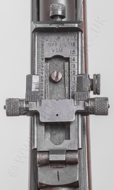
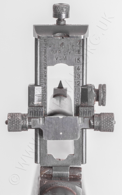
Below: three close-up views of the Peddie sight
 >
>
 >
>

18,130. Peddle, J. T. Aug. 28. 1908


Sights.—In back-sights for small-arms provided with a screw-actuated wind-gauge slide, the defects due to back-lash are obviated by providing the screw i, Fig. 3, at each end with a knurled head l, e bearing respectively upon two semi-cylindrical bosses b on the slide a, which moves longitudinally along the leaf d. The sight-bar g is preferably of square section Fig. 4, and has extensions k which correspond with the semi-cylindrical bosses b and prevent access of grit &c. to the screw i which is thus completely enclosed. The sight-bar may be provided with notches m, n, or with peep holes, the latter being above, or below, or both, as desired. In the modification shown in Fig. 6, the boss b is recessed to receive the extension k on the sight-bar. In each case the heads l, e are graduated to read with zero-marks on the slide a the graduations being arranged in reverse order. The invention is applicable to the sight described in Specification No. 6074, A.D. 1908.
19,536. Calichiopulo, A. Dec. 5, 1908, [Convention date].

Sights. — The fore-sight consists of a circular opening in a tubular piece e, the periphery of which is designed to leave only a thin annulus of light between itself and the inner periphery of the circular back-sight when the two are in proper adjustment. The Specification in the original form, as open to inspection under Section 91 (3) (a), comprises also sights of other than circular shape and provided with means for centreing the object in the sighting-aperture. This subject-matter does not appear in the Specification as accepted.
5807. Peddie, J. T. March 10. 1909

Sights.—Relates to leaf sights of the type, described in Specifications 6074/08 and 18,130/08, in which the side portions of the leaf on which the cross-bar slides are capable of a limited longitudinal movement for fine adjustment, and also to sights of this type provided with notches for the pawls of the cross-bar corresponding to the principal range graduations, and consists, firstly, in providing the range graduations on the movable side members b in order to ensure that a single fine adjustment made for one range is sufficient for all other ranges, and, secondly, in the provision of a drift slide. The cross-bar c has spring pawls g which engage notches l in the side members corresponding to the graduation marks. The scale v for fine adjustment is marked on the leaf. To adjust automatically for drift, the leaf is formed in known manner with an inclined guideway in which the sighting-plate n slides, the plate n being mounted in the cross-bar e so as to be capable relatively of lateral movement only.
8736. Swift, A. E. April 13. 1909
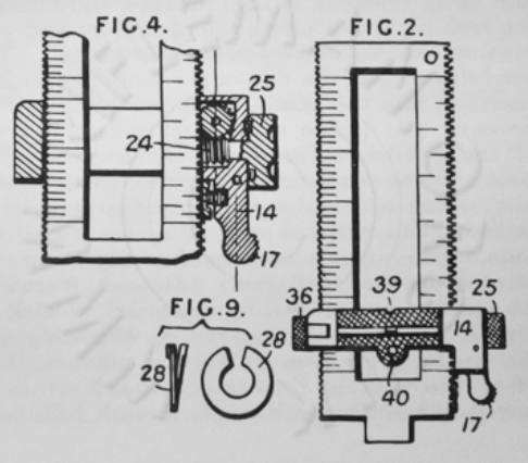
Sights.- Relates to back-sights in which elevating-means comprise pinions, carried by the sight-bar, and racks on the leaf, and consists mainly in the arrangement to secure fine and coarse adjustment and in a clicking-indicator. 'The elevating-pinion is mounted at one end of a pivoted lever 14, the other end 17 of which can be pressed in to disengage the pinion. The pinion is rotated by a worm 24 having a milled head 25. The clicking indicator consists of a split spring washer 28, Fig. 9, having bent ends, one of which engages notches on the underside of the head 25 of the worm 24, or of the head 36 of the wind gauge adjusting-screw. The sight-plate forms both an open notch 39 and an aperture 40. When it is desired to have the aperture uppermost, the whole sight-bar is reversed, the pinion then engaging the rack at the other side of the leaf. To prevent reflection, the surface of the plate is roughened.
17,482.Clifford, W. J . July 27. 1909
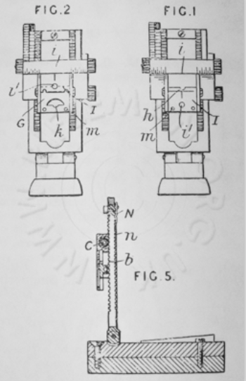
Sights. - Relates to back-sights of thc kind in which the notched sighting-plate is provided with a vertically-slideable aperture plate which can be raised to bring either the aperture, or the straight top edge, into alignment with the notch, and consisits (1) in providing a U-notch h instead of a V-notch, and in providing the sighting-plate G with a second notch k, Fig. 2, with which the aperture can also be brought into alignment. The vertical slide I, having the aperture i1 and straight top edge, has its movement limited by stops i, m. The sighting-bar is elevated by a rack and pinion b, C, Fig. 5, and provided with a clicking-spring N, which engages notches n at the back of the leaf.
22,132. Dawson, Sir A. T., and Peddle, J. T. Sept. 28. 1909

Sights.—Relates to tubular fore-sights, and consists in so shaping them as to avoid the reflection and diffusion of light therefrom to the observer's eye. The outer upper surface a2 is tapered towards the remote end; and the inner surface is so shaped that the remote end of the aperture is not presented with a diminished diameter at the greatest angle of elevation. In the form shown in Fig. 1 this is accomplished by flaring the lower part a4 and in that of Fig. 5 by providing a small inner aperture by means of the flange a5.
30,280. Boult, A. J., [Sutherland Riflc Sight Co.]. Dec. 28. 1909

Sights.—Relates to hinged-leaf-and-slide back sights, which are provided with a pivoted base for lateral adjustment, a sight plate corrected or drift by inclined grooves in the leaf, and coarse and fine adjustment for the slide. According to the invention, two pawls 20, 21 engage the same side of the elevating-screw C. and are interlocked hy projections 27, 28, so that pressure on a thumb-piece 29, on one of the pawls, disengages both pawls from the screw with which they are normally kept in gear by springs 25, 26. The slide D is formed of pressed metal with one or more spring fingers 16, 17, 18, 19 adapted to grip the leaf A.
10. Bernard, W. Jan. 1. 1910
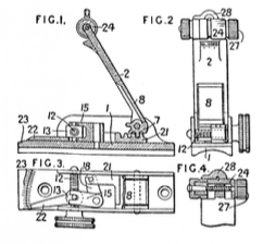
Sights.—Relates to what are known as "lift up" sights, that is, hinged-leaf sights in which the leaf is gradually raised for the different ranges while the sighting is always from the top, and relates particularly to the kind in which the leaf is raised by a transverse rotary member. According to the invention, the leaf 2 is raised and lowered by a tiansverse horizontal rotary member 12. The member 12 is geared to the leaf by a nut 13, a bell-crank lever 15,18, and a rack and pinion 21, 7. The elevation is shown by a movable pointer 22 on a scale 23 fixed to the base 1 and visible from the rear. The leaf 2 is connected to the pinion 7 by a spring catch 8, which permits the leaf to be folded down from, and raised to any set position without touching the operating-member 12. The sight-piece comprises a cylinder 24 having a groove forming an open notch, a hinged bridge 28 adapted to convert the open notch into an aperture sight, and a screw 27 for lateral adjustment.
21,507.Dawson, Sir A. T., and Peddie, J. T. Sept. 15. 1910

Sights. - Relates to lift-up sights of the kind comprising a leaf having, on its underside, cam-surfaces which enter a recess in the base-plate and which are engaged by a bar sliding on the base-plate, and consists (1) in making the leaf C with a straight upper surface when the leaf is in its zero position, lies parallel to the axis of the gun, and (2) in forming the upper surface of the leaf with a central fluting C1, Fig. 5, so the sighting-aperture can be placed low. As is known, the cams have lateral ribs engaged by the sliding bar, so that the leaf is positively depressed as well as raised.
13,218. Boult, A. 3., [Canada Tool and Speciality Co.]. June 1. 1911
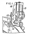
Sights. - Relates to backsights, for rifles of the Lee-Enfield type, of the kind in which the sight is carried on a bridge-piece mounted at the side of the action- body, and consists in forming the bridge-piece with two clamps 12, 13, for attaching it to the existing aperture sight F, and two spaced arms 18, 19 for supporting the two extremities of the sighting-leaf D.
Return to: TOP of PAGE
See this website's Raison d'être
