THE YOULTEN HYPOSCOPE
A Trench Periscope sighting
attachment for the SMLE rifle
A Trench Periscope sighting attachment for the SMLE rifle
Below: the adapter viewed from the right-hand side of the butt-stock
During the First World War, this device was advertised for private purchase at £7-1s-0d (£7.05), at a time when a high-quality target-standard "Long" Lee-Enfield rifle could be purchased complete for between £7 and £8. The new " short" rifle was being sold, by the various manufacturers, to the Government for little over £3.
Youlten applied for his first patent for this particular advanced device in 1914, and it was granted on October 2nd., although his initial invention had been mooted more than ten years earlier. The preceding idea, after the Boer War, was for one of the earliest trench type periscope arrangements, latterly adapted as a remote sight for rifles and even artillery.
We cover the more well known First World War hyposcope first, as it is the device for which most researchers seek information; but Youlten's earlier work is comprehensively discussed in a report in the Daily Mail in 1902. This is replicated further down the page prior to the report of the proceedings of the Small Arms Committee in January 1903 on the submission of Youlten's early hyposcope for trials with a view to adoption by the military.
_________________
The October 1914 Patent application for the WW1 device.
20,439. Youlten, W. Oct. 2.
Sighting - accessories: Consists in forming a hyposcope of a single
double-reflecting prism, Fig. 2, having a vertical rectangular face 5 opposite
and at right-angles to the line of the sights, lower and upper rectangular totally-reflecting
faces 3, 1, a rectangular face 6 opposite the eye of the marksman, and
two trape¬zoidal side faces, the prism being enclosed in a casing 7, Fig.
i, which leaves the faces 5, 6 exposed and is preferably mounted so that it
can be raised and lowered behind the V or other sight. The casing 7 is provided
with a retaining-strip 8 of angle section for holding the prism in position,
and with hinged flaps or shields 12, 13 for the faces 5, 6. A geometrical construction
for determining the shape of the prism is described.
The patent for the finished article was granted
just after Christmas in 1914
24,687. Youlten, W. Dec. 28.
Sights; sighting - accessories:-
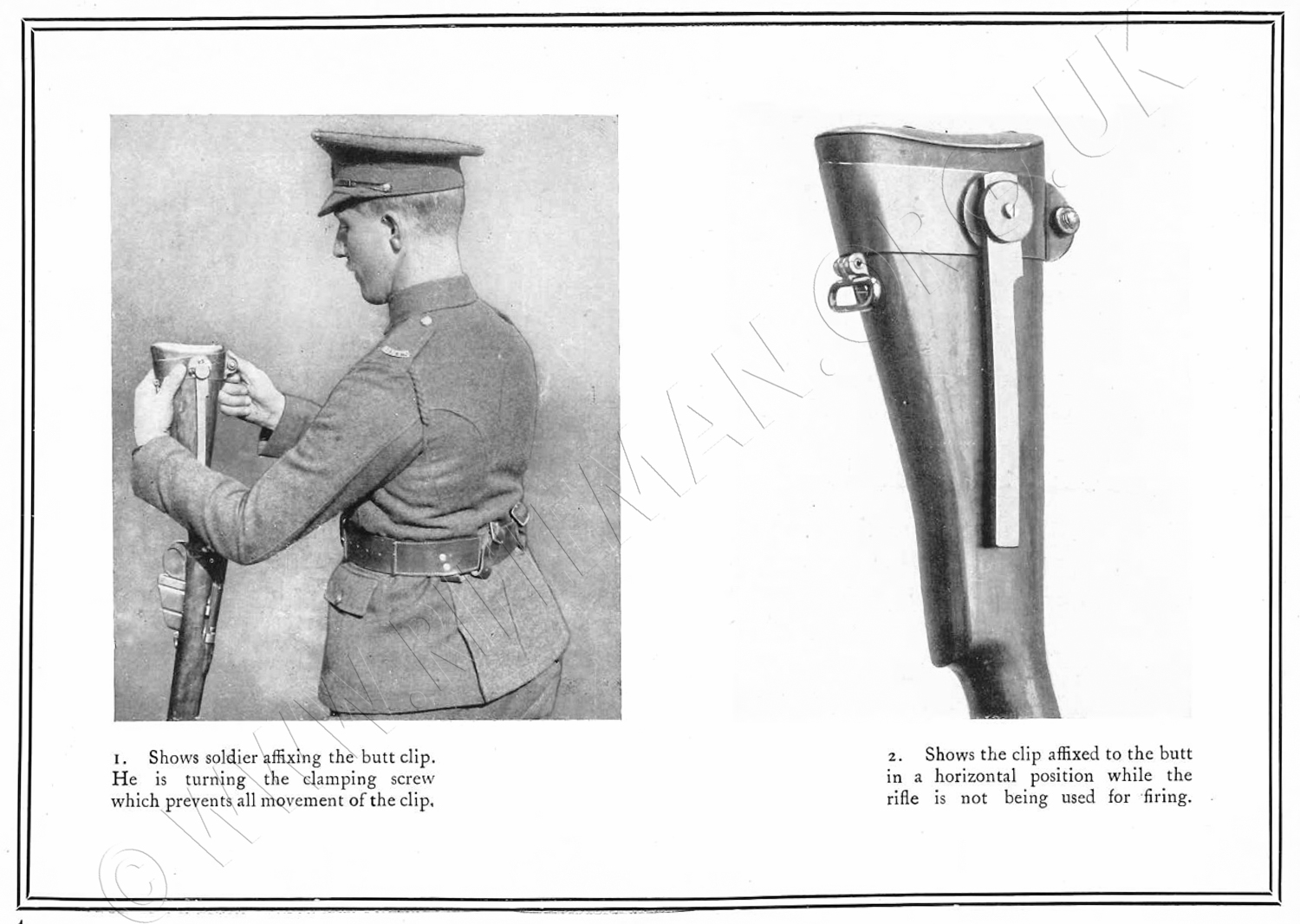
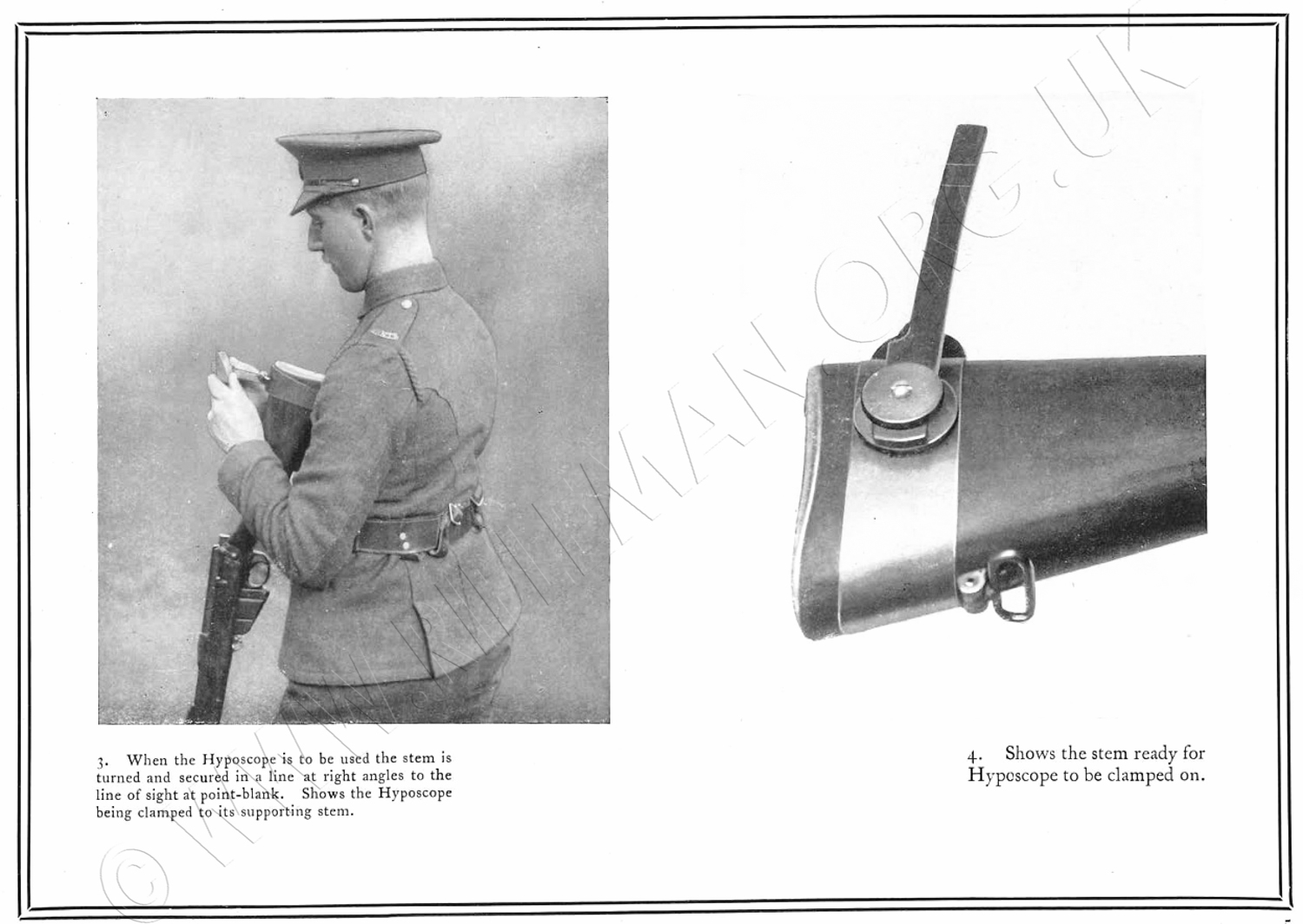
Relates to means for attaching hyposcopes to rifles or other small-arms, and consists in the combination of a clip 7 adapted to be passed round, and clamped to, the stock of the rifle near to the butt end, and a stem 12 carrying a prismatic or other hyposcope 18 centrally behind the sights, the hyposcope deflecting the line of sight downwards over the butt. The stem 12 is preferably hinged to the clip 7 and provided with means for locking it in the raised or lowered position. The stem may be telescopic, or may consist of a system of levers. The Provisional Specification also states that the backsight may be dispensed with, range indications being provided on the stem and a suitable sighting-mark provided on the hyposcope , and also describes a construction of hyposcope comprising a wide upper mirror and one or more smaller reflecting-surfaces at a lower level.
The unit came in a small wooden box, and could be quickly attached to a No.1 SMLE rifle or indeed any Enfield derivant with similar stocking dimensions. An instruction sheet, shown in greater detail in a lower image, was glued to the inside of the lid in customary contemporary fashion.
 ...
...
The lid of the box
carried the now
rather indistict stencilling
.......................
" YOULTEN'S
 ............RIFLE BUTT HYPOSCOPE
....................SUPPLIED BY
......PERISCOPE HYPOSCOPES LTD
.................WESTMINSTER S.W. "

Left: the front face of the prism
viewed over the rear-sight
from the muzzle of the rifle.
Below: the sight picture.
Looking up through
the base of the prism
over the sights
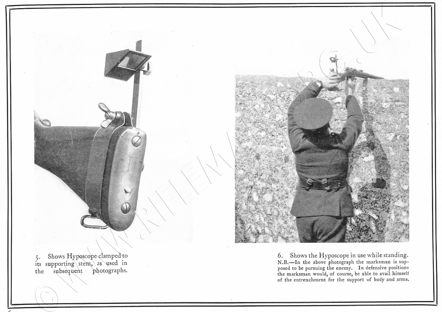
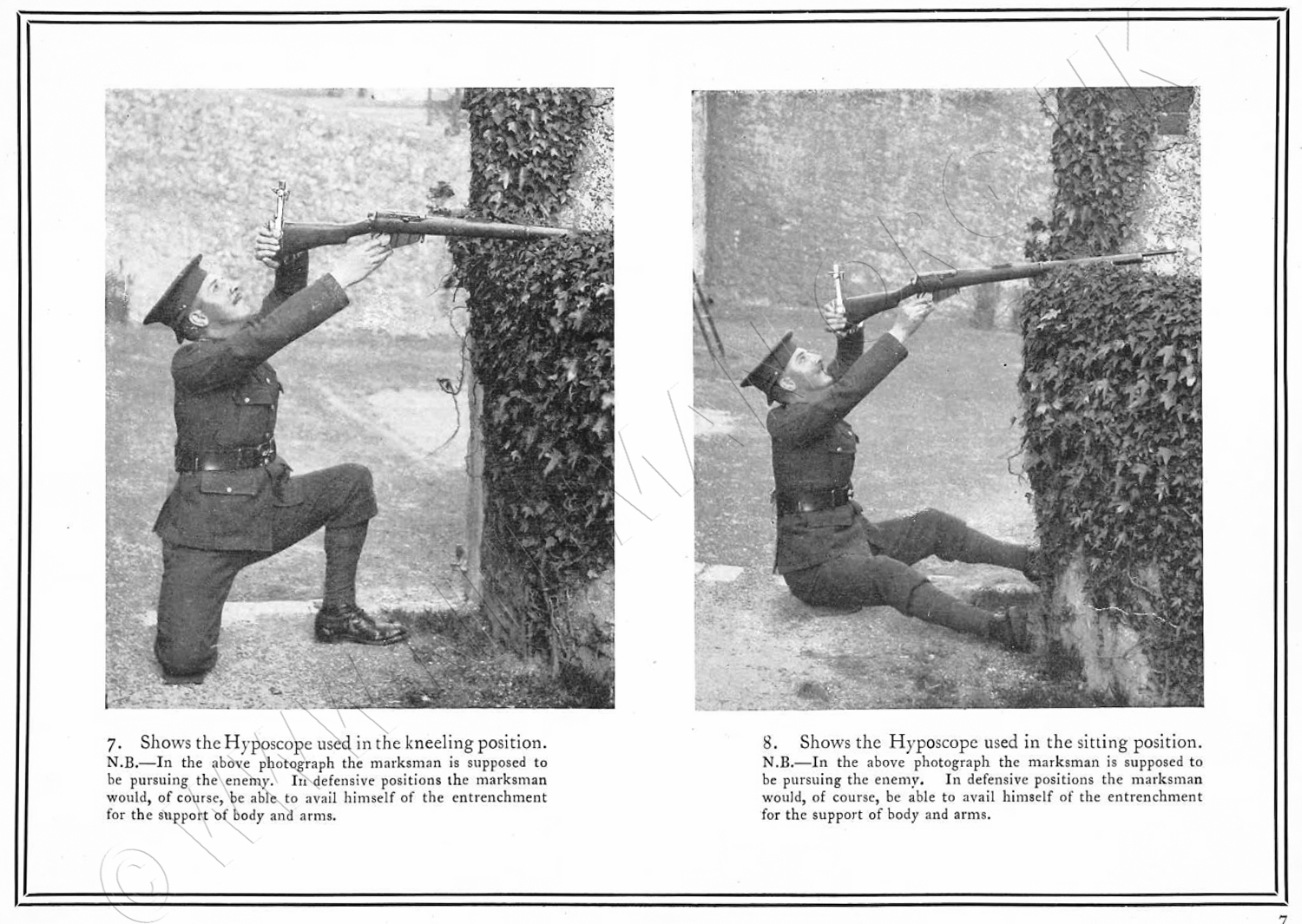
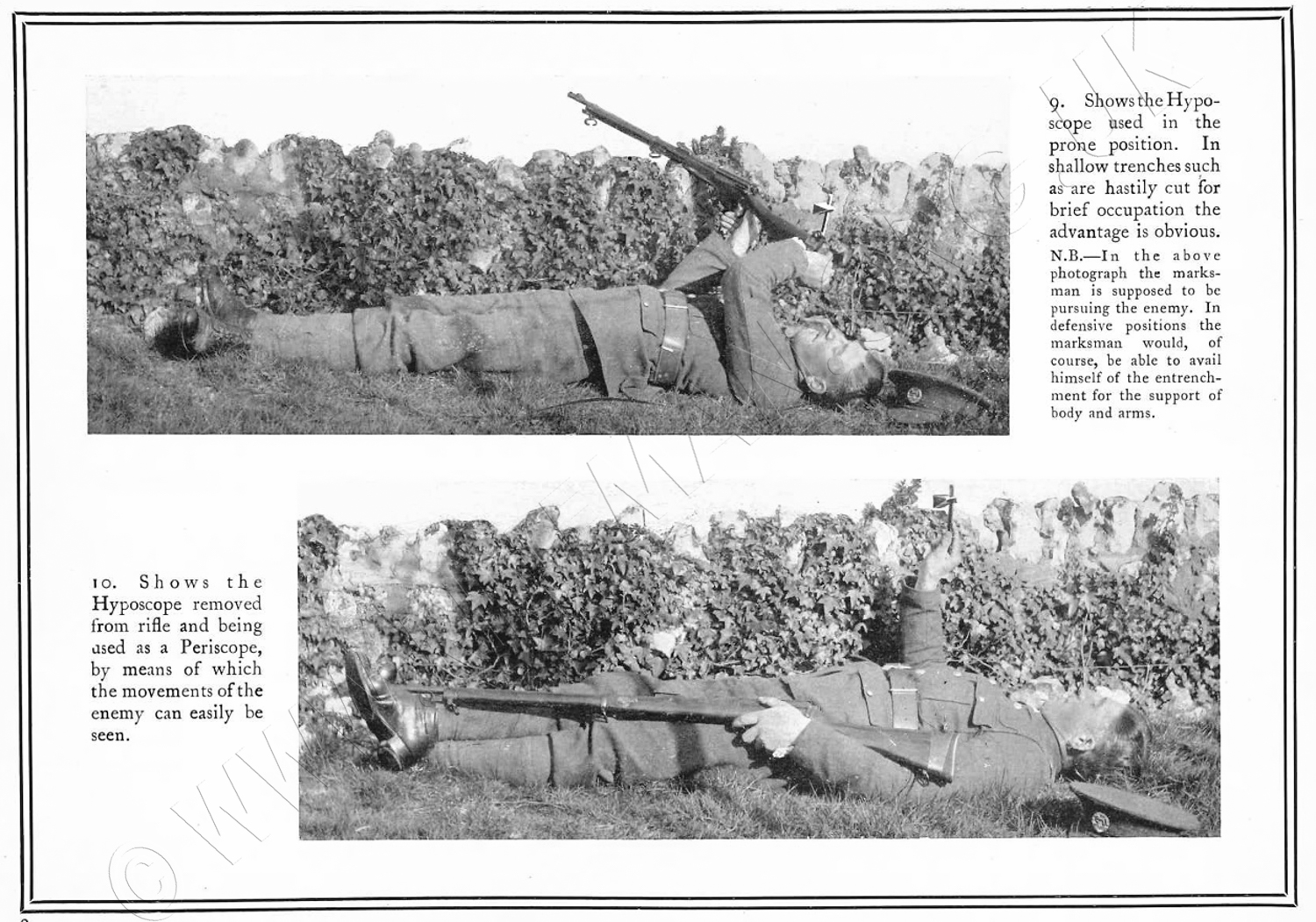
 With the firer standing on the fire-step,
the rifle would, most commonly,
be rested on the trench parapet,
ideally on a sandbag,
or similar,
for stability and to protect the right forearm,
then held with the right hand holding the wrist of the
butt-stock and with the fore-finger on the trigger in the usual way.
The left hand would be used to grip the butt-plate, with the left fore-arm above the head.
Sighting could then be accomplished by tilting the head back and looking through the underside of the prism.

In March 1915, Youlten was granted a further patent for a modified prism design,
now additionally in the name of the company Periscopes and Hyposcopes Ltd.
In January of that year he had already patented a design, no. 480,
for a hyposcope which could be "attached to the backsight of a machine gun".
 3496.
Periscopes & Hyposcopes, Ltd.,
and Youlten, W. March 4. Sighting - accessories:-
Consists in forming a hyposcope of a single prism having (1) a front face normal
to the line of sight, (2) a first reflecting-surface which is total-reflecting,
and (3) a second reflecting surface which is silvered or otherwise converted
into a mirror. In the prism shown in Fig. 2, the reflecting surfaces 19, 18
make angles of 60 degrees and 90 degrees respectively with the front face 17,
and the ray is deflected through 60 degrees. In the prism shown in Fig. 6, the
reflecting-surf aces 24, 23 make angles of 45 degrees and 112½ degrees
with the front face 22, the ray being deflected through 45 degrees. A prism
constructed according to this invention may be combined with other reflecting-surfaces
which first deflect the sighting-line sideways and then backwards.
Youltens' inventive ideas for sighting aids were prolific, and he subsequently designed an elaborate rifle optical system along the lines of the Lattey, Neil and Gibbs Galilean products, but again also for possible utlisation on a machine gun.
This unit received its patent grant in August 1915.
11,227. Youlten, W. Aug. 3. [Cognate Application, 1163/16.]
Sights; sighting-accessories: -
Relates to optical sights of the kind in which a half object lens or com¬bination,
and a half eye¬piece lens or combination are so mounted with re¬spect
to the Ordinary sights that an open sight can be taken and, at the same time,
a magnified image can be seen. Accord¬ing to the invention the object lens
is mounted in a carrier adapted to be clipped or otherwise attached in close
proximity to the foresight, and the eyepiece lens is mounted in a carrier adapted
to be attached to the V or equiv¬alent part of the backsight so that it
moves there¬with. Figs. 1, 3, 4, 5, and 6 show the invention applied to
a service rifle. The eyepiece lens t, Figs. 3 and 4, is mounted in a carrier
s provided with clips 2, 3 and a screw, 4 for securing it to the ordinary V
sighting plate, in such a position that the bottom edge of the lens is level
with the top edge of the sighting-plate. The object lens h, Figs. 5 and 6, is
mounted in a carrier g fitting, by means of a dovetail joint, in a base-plate
formed with a clip a, b for securing it to the gun. Figs. 8 and 9 show a method
of securing the eye lens 13 to the backsight of a machine gun. The lens is mounted
in a carrier 12 which is attached to a plate 8 adapted to be clipped to the
sighting-plate. The lenses may be adjustable. A hyposcope may be combined with
the eye lens.
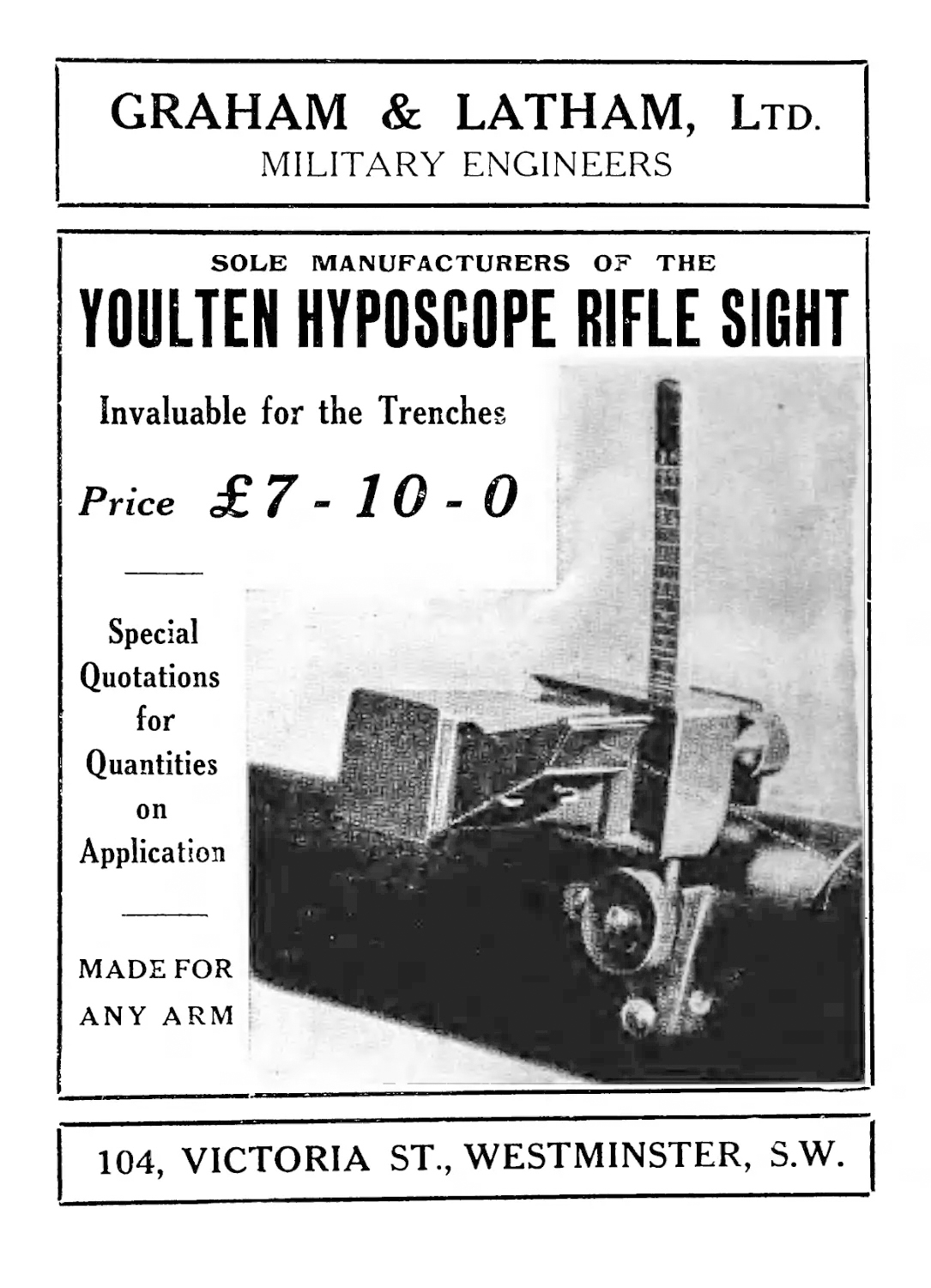
At seven pounds and ten shillings (£7.50) it was then not a cheap item.
At about that time, the company issued a small brochure giving details of their product.
 \
\
_________________
Although the patent for the already discussed First World War device was acquired early in that conflict, there then being a genuine need for such equipment, a less sophisticated unit had been offered to the military for assessment ten years earlier.
In September 1902 the Australian Evening Star newspaper published a report that had appeared initially in the Daily Mail in the U.K.
It makes for the most interesting reading, perhaps showing an ill-found optimism for the potential benefits of Youlten's "new" invention, in a situation that preceded highly significant changes in the manner in which war was to be waged in conflicts that would far exceed the cicumstances that held sway in the then most recent South African Boer Wars.
The Evening Star – September 1902
TO REVOLUTIONISE MODERN WARFARE
“If you can perfect this little instrument you will revolutionise modern warfare. Nay, more; you will help to put an end to war altogether”.
This was the remark which a famous general made to Mr. W. Youlten twelve months ago, after examining the model of an appliance to be fixed to rifles or guns invented by the latter. Mr. Youlten claims that he has now perfected the instrument, which he calls the “hyposcope”. Briefly, by means of the hyposcope, a soldier is rendered invisible, while to him the enemy remains clearly in view. Mr. Youlten asserts that if our forces in the late war [Ed: the 2nd Boer War] had been provided with the hyposcope the Boers would have expended their shot and shell on vacant air. Thousands of brave men now lying under the veldt would have been restored to their families. The war would have been concluded long ago, and scores of millions of pounds saved to the British taxpayer. This is a great deal to claim for a little instrument made out of two brass tubes and four mirrors, and costing no more than a sovereign, but Mr. Youlten’s opinion is shared by some of the greatest military authorities in England. The War Office has taken up the matter seriously. Earl Roberts has experimented with the instrument, Viscount Kitchener has watched the results achieved by it, the National Rifle Association offered a special prize for the best shooting with it, and all the representatives of foreign armies in London are waiting almost with bated breath to learn if the War Office has decided to add this wonderful little appliance to Tommy’s fighting kit. Such an important step may be taken almost immediately, in which event every British soldier will be seen wearing at his waist belt a leathern pouch not unlike a pistol case. It will contain his hyposcope – the instrument which will make of him an invisible fighting man.
The hyposcope may be attached to either rifles or guns. It is a telescope-like arrangement which in five seconds can be fitted to th breech. Transferring lenses show th entrenched soldier the exact position of the enemy, while all the latter can see, even with the aid of powerful glasses, is the rim of his rifle muzzle.
“If the twenty million rifles of Europe were fitted with the hyposcope” said Mr. Youlten, “the probability is that the likelihood of a great European war would disappear forever. Two opposing armies entrenched would see nothing to aim at. It would be a game of ‘blind man’s buff’, if I may use the expression. All they could do would be to pound away at the trenches with their artillery, or, as a great soldier said to me, ‘the guns of one army would have to blow away the side of a hill before they could see anything to kill.’ ” The trials with the hyposcope at Bisley have proved highly successful at the time of writing. Five bulls in succession have been gained by one marksman, while the score of another was 4,5,4,4,5,2.
“It was after Colenso” said Mr. Youlten, “that the idea occurred to me. I felt depressed at the number of men we had lost, and marveled at the fact that our troops could not see a Boer to shoot at. I immediately began to ponder the question whether it would not be possible to render entrenched men invisible. Then I thought of a toy which, when a schoolboy, enabled me to look over walls without myself being seen. Here was the germ of the invention. I at once got a workman to make me such a toy from my own design. It was back the same afternoon. The following day a member of the Ordnance Committee of the War Office happened to visit me. I I explained the thing to him, together with certain modifications and improvements I intended to introduce. The officer took the instrument away with him. When I returned from luncheon there was a telegram awaiting me. It was from the War Office ordering a thousand of the instruments. The invention at that time was intended only for observation purposes. Since then I have developed it considerably. General Woodgate would not have lost his life had he had one of these instruments. In the great fight with De la Rey in April the entrenched Canadians held their post until every man was killed or wounded. I venture to say that the hyposcope would have saved every one of these precious lives. I could give you a hundred such cases. In one battle a distinguished officer whose name I am not at liberty to mention had forty men shot one after the other as they went to serve a Maxim. ‘To tell a man to serve that gun was like sentencing him to death,’ said the officer. If, “ protested Mr. Youlten, “ that Maxim had been furnished with a hyposcope, not only the men, but the gun itself, would have been invisible except the barrel.”
Mr. Youlten’s invention has been praised by some of the greatest soldiers in England. One authority declares the “ the hyposcope will render every one of our men worth two”. The money value of a soldier to the War Office is fixed at £300. On this basis, provided with a hyposcope, he would be worth £600. Should a great war break out many eminent authorities agree that not a soldier could be safely spared from England or from India. That is the reason why the War Office urges every Englishman to become an efficient shot. But it may be that the hyposcope will solve this problem of home defence. At any rate, the implement is now on its trial, and a few weeks, or even days, will decode whether something like a revolution is to occur in the methods of European warfare.
London ‘Daily Mail’.
____________
This earlier device received a favourable report after trials, and the archives of the School of Infantry's Weapons Collection - to whose curator we are grateful for permission to replicate the material - contain the minutes of the relevant Proceedings of the Small Arms Committee. Item number 103 (SIGHTS), of minute reference number 712, replicated below, details the report and conclusions.
_______________
Confidential.
PROCEEDINGS OF
THE SMALL ARMS COMMITTEE.
26th January 1903.
MINUTES 712 TO 714.
President.
COMMANDANT,
SCHOOL
Members.
SUPERINTENDENT, ROYAL SMALL ARMS FACTORY,
CHIEF INSPECTOR, WOOLWICH
CHIEF INSPECTOR OF SMALL ARMS
NAVAL MEMBER
SUPERINTENDENT, ROYAL LABORATORY
DISTRICT INSPECTOR OF MUSKETRY,
Secretary.
DEPUTY ASSISTANT DIRECTOR-GENERAL OF
ORDNANCE (0. 7)
Associate.
* On leave.
103. SIGHTS.
Mr. Youlton's proposed Hypo-telescope.
Previous Minute 705 v.,
12.1.1903
D.G.O., 23.1,1903, forwarded the
following description by the inventor of his proposals — improvements on the hyposcopes previously submitted :—" The range-limit of the rifle hyposcope used at Bisley, and
tried at Hythe, was 600 yards. The latest model has the
following advantages :—
1. It can be used at any range shown on the backsight of any rifle.
2. Shooting may as accurately be continued without the ordinary rifle backsight as with it ; equivalent to an additional backsight should that on the rifle be rendered useless.
3. The elevation of the hyposcope equivalent for the rifle backsight can be accurately, and at once, effected by a screw. This is placed several inches below the rifle backsight, so that the needful elevation can be obtained without moving the rifle from any rest, or exposing any part of the marksman to the enemy.
4. A lateral wind-gauge is provided on the hyposcope. As this is quite independent of the V of the backsight, a man may, without lowering his or taking his finger from the trigger, instantly aim in a different direction to that for which he may have made wind allowance; for in the eye-mirror of the hyposcope, both the movable wind-gauge (vertical) line, which acts as a backsight, and the fixed V, are visible — thus either may be instantly utilised at will.
5. In full view of the marksman is a table of wind allowances.
6. The tube of the new instrument is square, instead of round, the field of view (6') being therefore much larger.
7. Any 'cant' of the rifle from its vertical axis is visible in the sighting focus.
8. A reliable telescopic sight is also added, for which the elevation scale of the backsight mechanically (not visually) utilised.
Up to 2,000 yards, a ' Hypo-marksman' can now take steady aim, with his head as well as body in perfect safety below any available cover from 12 inches upwards, with the choice of using his natural vision, or (in one second) a reliable telescopic-sight. He also possess the advantage of a fired wind-gauge and 'cant' indicator, as well as the additional backsight mentioned."
Mr. Youlton attended the meeting to further explain details.
The committee are of the opinion that this is an instrument very well designed for its purpose and suggest that a small number be purchased and issued to commands for trials, and report as to whether such an instrument would be a useful addition to the soldier's equipment for service. It is for consideration if this instrument would not be a useful addition to the equipment of permanent fortifications either in its rifle or ordnance form.
VIEW THE ABOVE ARCHIVE AS A PDF
It should perhaps be borne in mind that at the time of this 1903 report in the Small Arms Committee minutes, the new Short Lee-Enfield had only just been first produced.
See also the Chandler Periscopic Hyposcope Lee-Enfield rifle adaptation
For Enfield and Lee-Enfield training rifle accessories and adaptations, see also: Miniature calibre adapters and conversions
Should you have an unusual Lee-Enfield small-bore rifle conversion and be willing to provide photographs, then we would be grateful to receive details.
Full acknowledgement of any published images would be afforded.

