LSA Eccentric Rear-sight
Please be aware that some specialist imagery may take time to load.
This site is for dedicated researchers and is best viewed on desk or laptop.
There have been queries relating to the elevation arrangement on the models of the folding aperture rear-sight manufactured by the London Small Arms Company with its unusual eccentrically-adjusted windage disc.
Acknowledgement and thanks must go to members of the U.K. Historical Breech-loading Small-arms Association (H.B.S.A.) for their kind provision of information and imagery for this article.
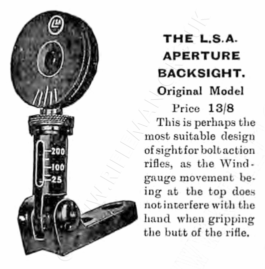
It has been observed that, unlike the BSA Model No.8 equivalent sight, which was produced in a number of different heights to suit various rifles with differing stock comb designs, the LSA sight was only made in one height, as far as has thus been observed here.
This resulted in difficulty in mounting the sight to ensure that the range yardage calibration agreed with that of a rifle's tangent-leaf barrel-mounted rear-sight.
Should you have knowledge of any variants not shown on this page we would be most grateful for detail and images for the benefit of other readers and researching owners of rifles so fitted.
It is evident that the LSA sight was intended for use with the War Office 1906 Pattern Miniature Rifle (WOPMR), but it is often to be been seen fitted to other rifles.
However, even with the WOPMR mounting can be problematic, and it is noticeable that the production of butt-stocks is not entirely uniform; although they were all supposed to be manufactured to the dimensions of the Pattern Rifles submitted to the Ministry of Defence by both the Birmingham and London Small Arms Companies.
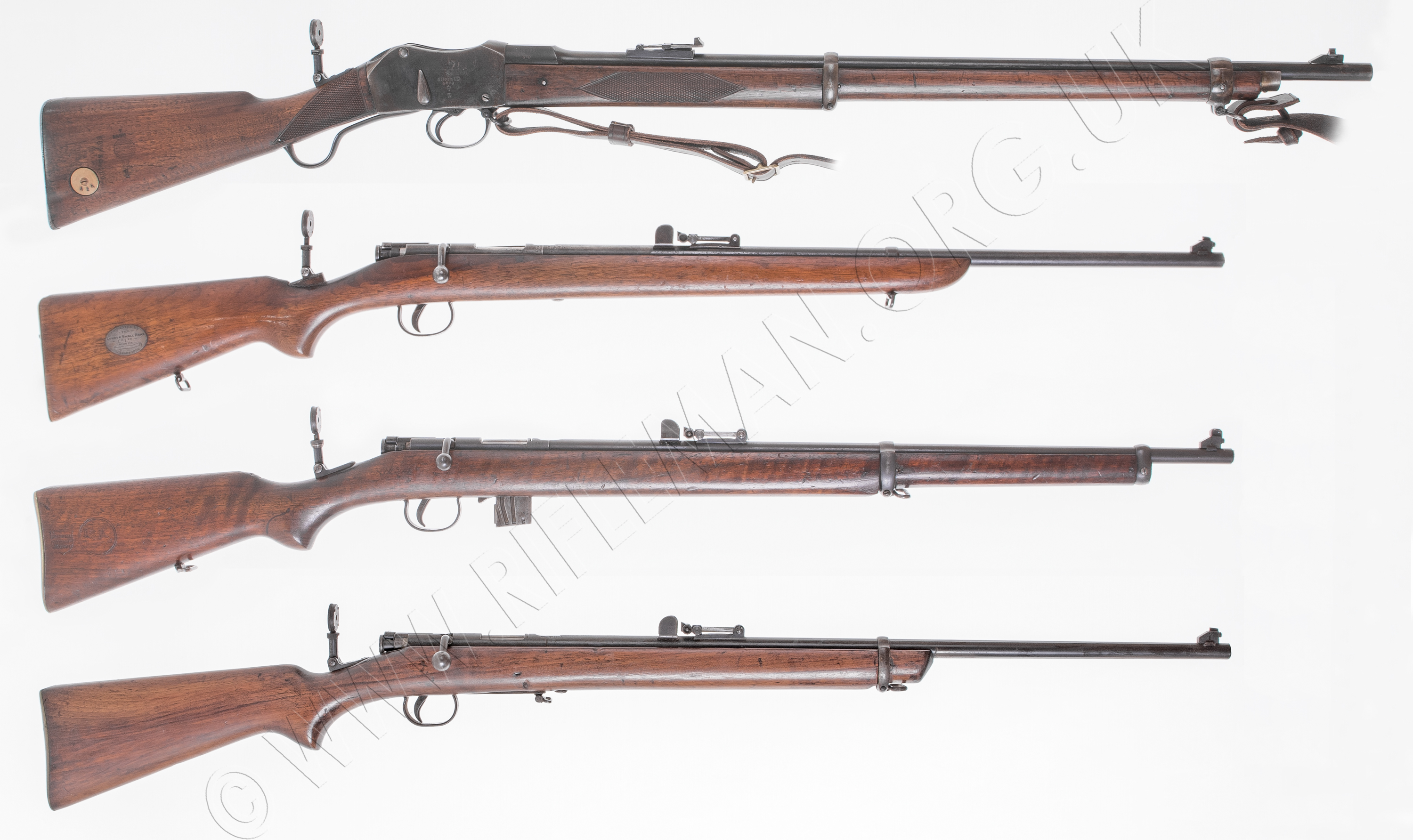
To illustrate the points mentioned, we have photographed four different rifles with the LSA sight fitted. Three of the rifles are LSA products, and one is BSA. In the image below, the upper rifle is an LSA conversion of a Mk.II/III Martini for the Society of Miniature Rifle Clubs. It carries the serial number 15639.
The second rifle down is a presentation example of a very early standard model carrying a silver butt cartouche indicating that the rifle was presented by the LSA Co., as a prize in the 1906 Cardiff open competition. The rifle is indeed the earliest we have come across thus far, with the serial number being 34.
The third rifle down is an LSA manufactured military-stocked magazine-fed modelwith the serial number 404.
The bottom rifle is a BSA made single-shot military-stocked model that has long ago had the front section of fore-end removed for unknown reasons. This is the only rifle here in .297/.230-inch Morris calibre; all the others being in .22 Long Rifle. The serial number is 8693.
Hover over or Click image to bring up hi-res file and magnifier
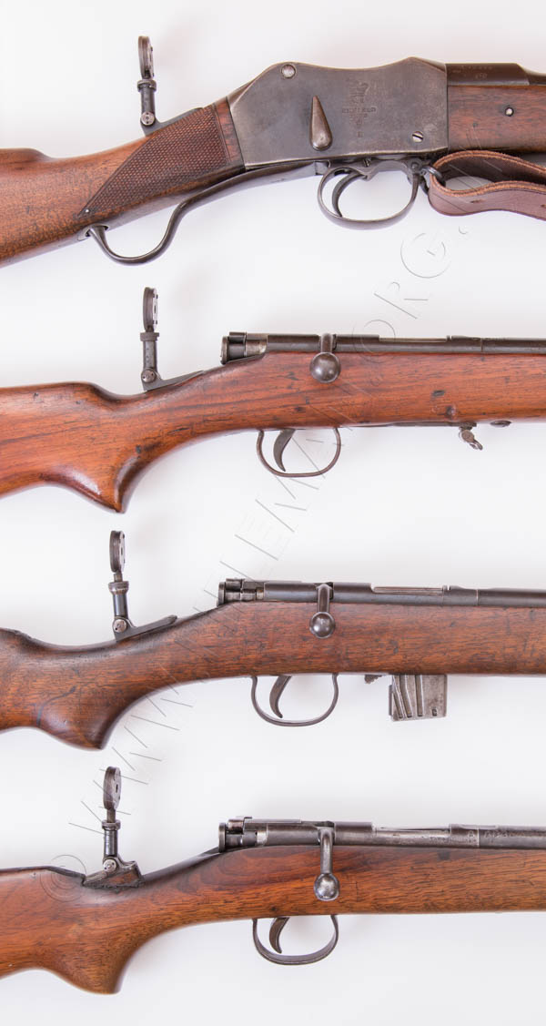
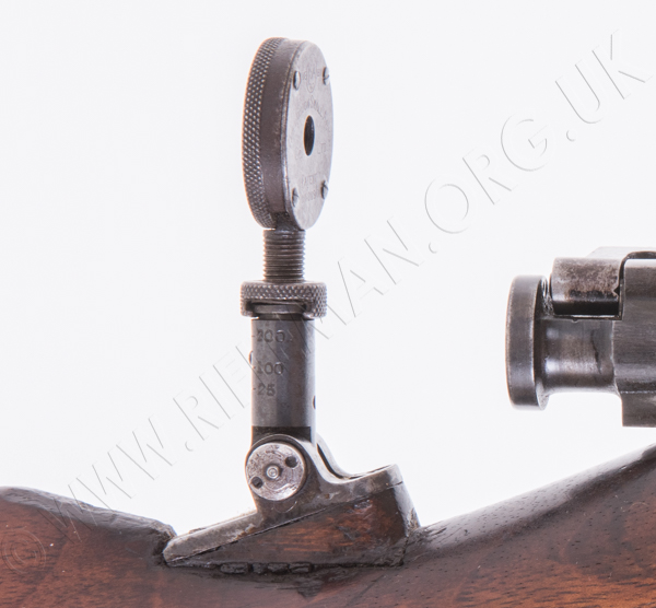
Another aspect relating to the positioning of the LSA sight on the wrist of the butt is that of clearance when the bolt is drawn fully open.
Depending upon the shape and slope of the rifle's butt comb and wrist, the sight needed to be moved back and forward to find the point where the range settings equated to those of the tangent rear-sight. This was evidently not as straight forward as shooters would have hoped, as many rifles have been afforded different cut-outs in the wrist, or even raising blocks, to achieve the necessary mounted height. The variation in butt wrist length and the semi-pistol-grip shape is far greater than might have been expected.
It could simply be impossible to mount the sight sufficiently far forward to gain the required height, and to clear the fully rearward movement of the bolt on opening, unless it was folded down between shots; not something many shooters would care to contemplate.
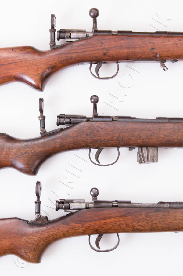
The images below show how three owners have 'worked around' such difficulties in the past.
 ....
.... 
The 1920 advertisement for the "Original" model sight is shown next.
The original 1908 Patent for the sight was via application No.11,809, under the applicants F.W. Bennett and C.S. Bayley on behalf of the London Small Arms Company, and there is a facsimile of this in the PDF further down the page.
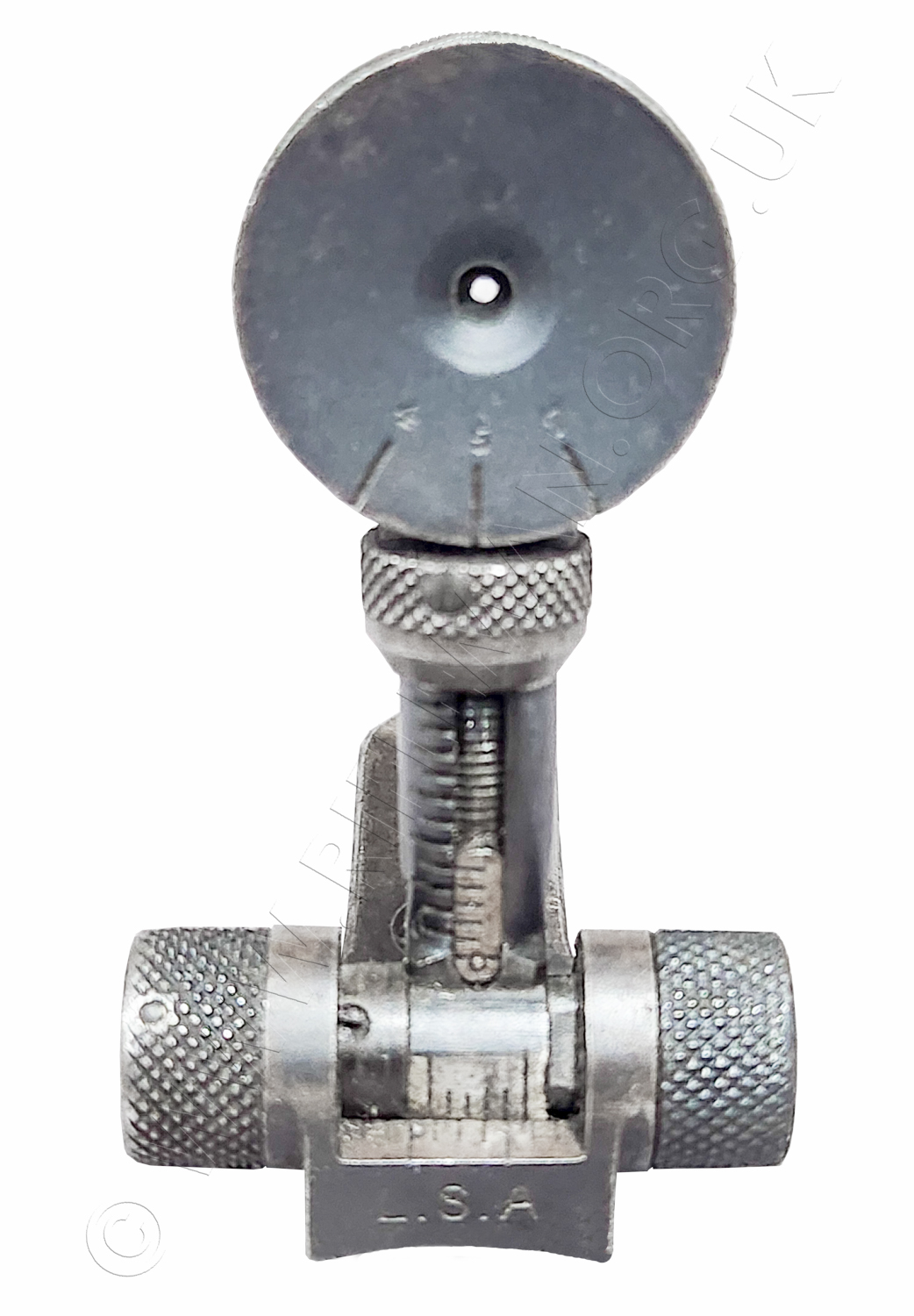
Here follows close-up imagery of the later and most common No.1 and No.2 variants of the sight.
We also later show imagery of the "Improved" model that is described in the advertising shown further down the page. That sight, very similar in outward appearance to those below, used the eccentric disc to afford three different aperture sizes instead of adjusting a single aperture for windage. Windage adjustment was obtained with a pair of knurled knobs, one each end of the sight's pivotting fulchrum; much in the same way as the BSA No.8 folding sight.
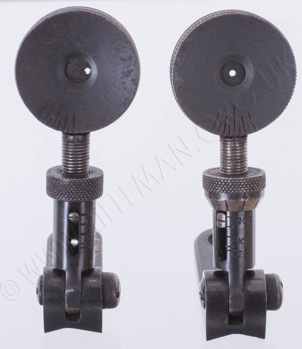
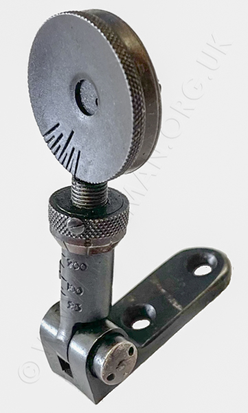
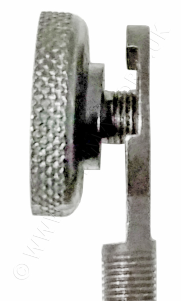
A No.1 model is on the right below, with the bevelled elevation knurled wheel.
A No.2 model is on the left, with the cylindrical elevation knurled wheel.

Among the confusing aspects of any research into these sights is the numbering of the variants. The sight described in the advertisement as the "Original" is the model No.2 in our images, although the naming may have related only to the then current eccentric windage adjustable sight rather than the first of that type. This was perhaps simply to distinguish between the disc of the original - adjusting windage, and the improved sight - adjusting the aperture size. However, we are aware of examples of the sight with the bevelled elevation wheel that have bases stamped No.2, so there is no certainty that the numbering bears any relation to variants either chronologically or model-wise. It is quite possible that, with comparatively low overall sales figures, and the intervening war, both old and newer stock parts were used simply to complete orders.
Both sights shown next are set close to the 200 yard calibration mark.
The five calibrated lines are for 25, 50 100, 150 and 200 yards,
but only the 25, 100 and 200 yard marks are numbered.
In the both images below, the No.1 is to the right;
 ......
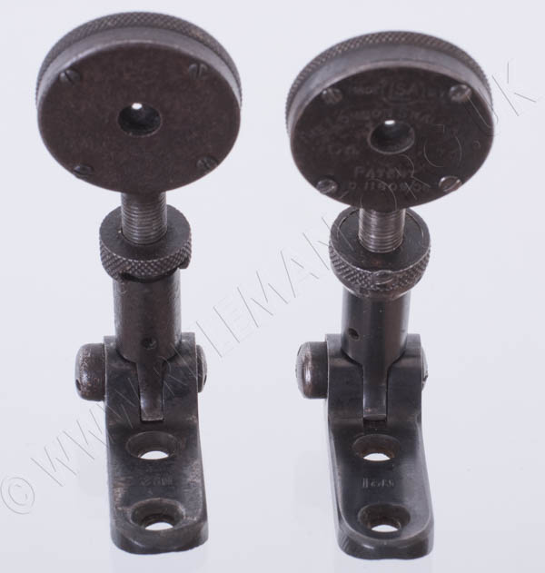
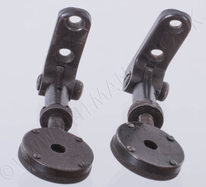
It is just possible to see the model numbers marked on the mount bases between the fixing holes.
In the left-hand image below, the No.1 is to the right;
in the right-hand image, it is to the left.
 ......
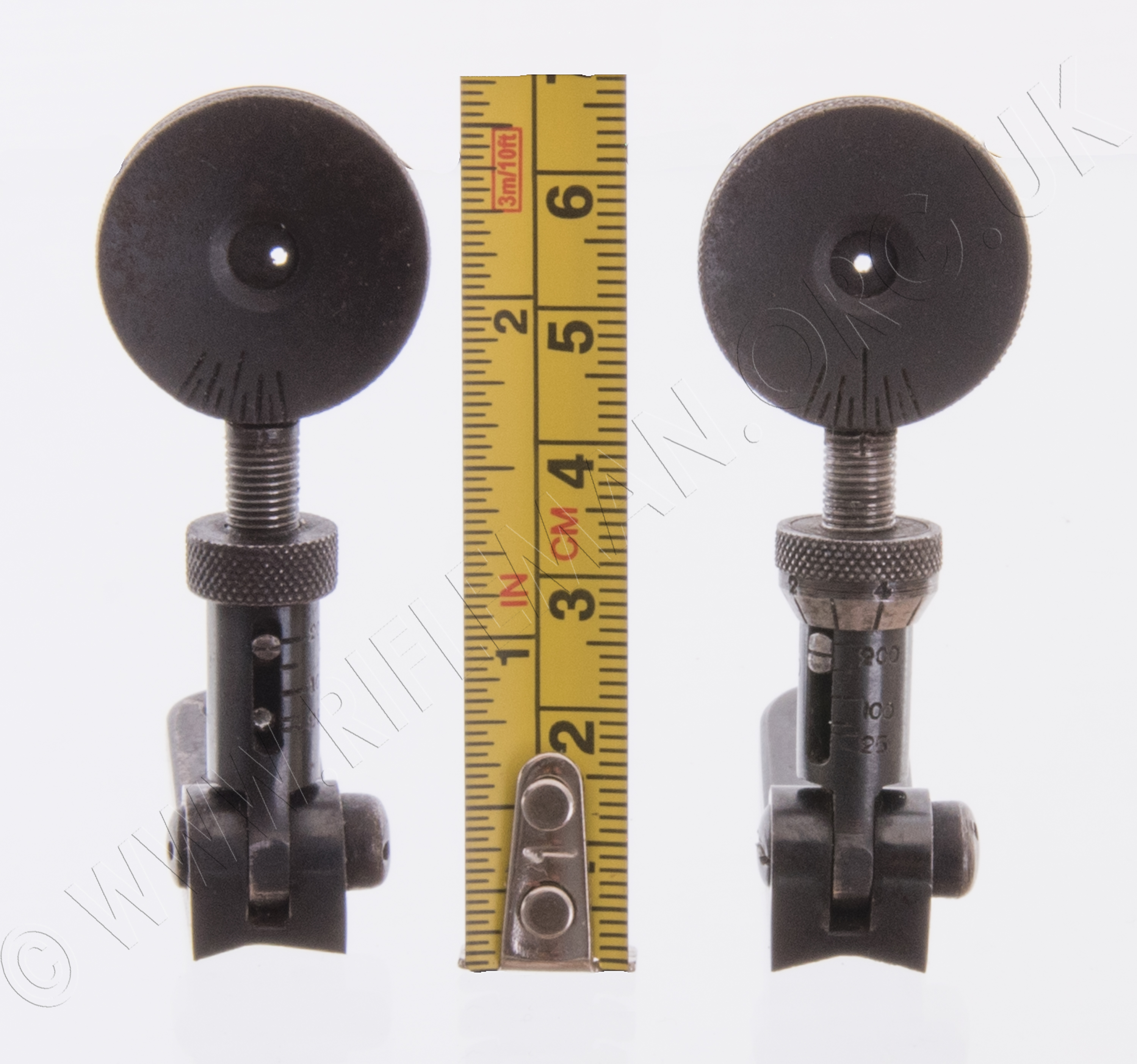
The two main variants are here shown with a rule alongside
Hover over or Click image to bring up hi-res file and magnifier
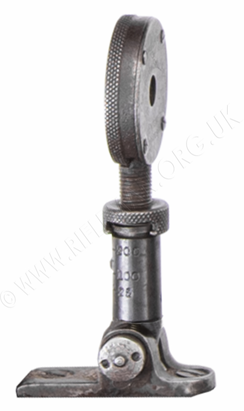
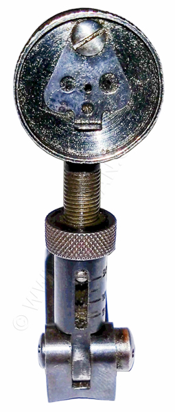
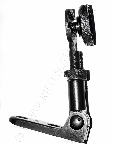
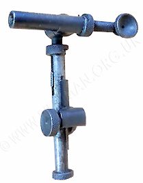
The only other sight variant, albeit rarely seen, is the earliest type, the one patented in 1908 under application No. 11,809. This is the model that is evidently a later retro-fit on the 1906 prize rifle previously illustrated, as it is crudely mounted to achieve the correct height. This is the very original design next represented. The sight has a shorter base, with fixings either side of the fulchrum, and is not numbered.
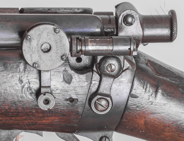
In the first image the bolt is in the fully open position, with the sight mounted in the narrowest point of the wrist, presumably to allow good clearance. With the sight fitted this way round, it has to be folded back, as is usual, and the butt-comb has been relieved to permit this; no doubt also allowing the rifle to be shot over the barrel-mounted tangent sight if required.
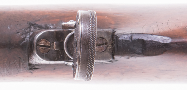
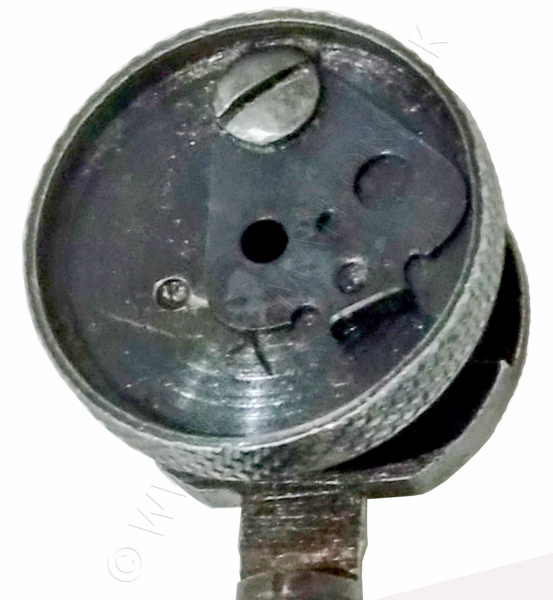
Photographed directly from above, the fore and aft mounting screw-holes are quite different from the bases of most later models seen, on which the fulchrum is at one end of the base and the two mounting holes are both on the same side of the stem.
The knurled elevation adjustment collar is the cylindrical one of the No.2 sight.
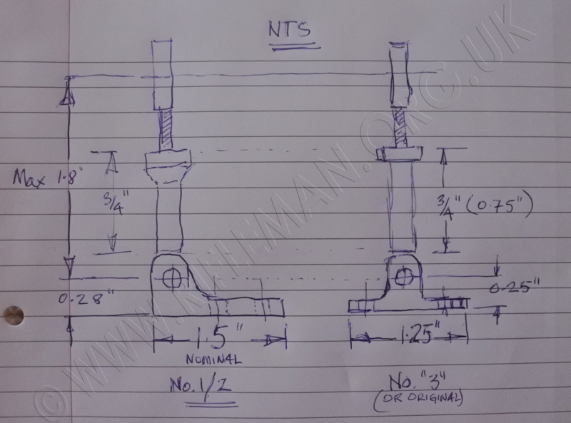
The base of this sight is 1.25" long compared with the 1.5" length of the Nos. 1 and 2 models.
However, the maximum height from the fulchrum to the aperture of 1.8", and the height of the solid lower section of the stem at 0.75" are identical to those of the Nos. 1 and 2 sights.
The thickness of the base is slightly less, being flat underneath, whereas the No. 1 and 2 models have a "V" base to accommodate the curvature on the top of the rifle's butt-comb without the need to cut out a flat area.
A rough sketch (not to scale) of the dimensions of the two sight types is shown below.
_________________
Two sights have been advertised for sale on a West Country gunsmith's website.
Both sights were described as No.2 models, but any numbering that may be on the bases is not visible.
The sight on the left is a perfectly standard model, but that on the right appears to have been modified in two ways. The disc casing has been disassembled by the drilling out of three of the four rivets, and a thicker replacement interior eccentric disc fitted with a large aperture. The rivets were replaced with screws shown in another photograph, but removed in this one.
It is unclear whether the aperture may be internally threaded for an additional eye-piece, but it is possible. If a larger aperture was the sole intention, that could have been achieved by simply opening out the original one. However, an additional eye-piece would have seriously reduced any lateral movement of the eccentric. We may never know the reasoning for the alteration, but there is one outside possibility that the windage adjustment was replaced by a home-made three-hole aperture disc along the lines of the 'improved' model, an example of which we have yet to see. Whatever the purpose, the sight has not been much improved in that respect.
More significantly, the bevelled adjustment collar of the No.1 sight has an additional split collar fitted above it. The two screws holding the collar in place appear to be locating in extension of the vertical slots in the threaded elevation spindle that prevent the disc casing from rotating.
Whether this arrangement, which presumably has increased the height of the eye-piece, was a factory modification or an owner's adaptation is unknown. If others appear then we may discover it to be the former.
 ............
The 1920 advertisement for the "Improved" model is shown below.
Any comparison is limited by the nature of the advert's imagery.
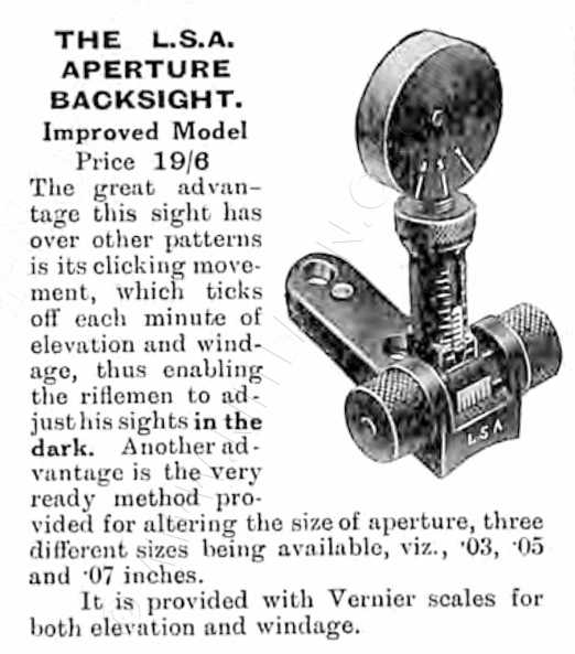
The disk now has just three scale lines indicating the position for each aperture size. The positions are almost certainly each indexed with an internal indent for positive location, in just the same way as the unidentified arrangement in the previous photographs.
Rather than the swivelling aperture plate in the unidentified eye-piece shown further below, the early 1912 Patent No. 1973, shown in our PDF, indicated that the three apertures were in a sliding cross-plate that was moved laterally by the rotation of the disc casing.
It is particularly worth noting that the elevation scale now has a vernier calibration rather than the plain five-line calibration of the original model. The new windage system also uses a fine vernier scale. The elevation screw now had clicks to permit more sensitive and accurate adjustment.
Whilst this model of sight was not specifically advertised for use with the War Office Pattern Miniature Rifle, the company's minutes for a Board of Directors meeting in 1912 make it clear that it was for that rifle that the sight was intended.
This presumably would also have been the case for the earlier sight of the 1908 Patent No.11,809 for the original sight.
With LSA production of the WOPMR understandably ceasing early in the First World War (1914-18), it is interesting to see that both the original and improved sights were still being marketed post-war, perhaps to dispose of pre-war stock. These sights were by then no match for the competing equivalents from the Birmingham Smallarms Company.
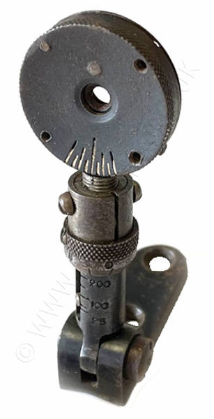
We have been kindly afforded images of the "Improved" model by a senior member of the HBSA (see links page).
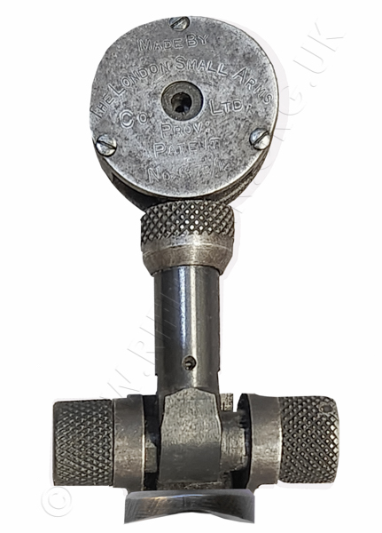
Viewed from in front, showing the Provisional Patent No. 1973 dated 1912 .
It is interesting to note that, while all the eccentric windage sights' discs, and that of the cross-slide side-mounted sight shown further down this page, are held together with four screws, the "Improved" model has only three.
and from the rear; the shooter's view of the elevation and windage scales;
each with its additional vernier scale.
The physical example has its three aperture sizes marked as 4, 5 and 7, whereas the advertisement described them as being 3, 5 and 7 - (for 0.03, 0.05 and 0.07 inches).
We hope to discover if the internal arrangement of this sight is that of the patent drawing,
but this would depend upon the willingness of the owner to disassemble it and investigate!
Apropos this "Improved" model, we also have been kindly sent images of a sight that perhaps achieves the same purpose, and is based on an LSA original model with a No.2 mount. However, there is a significant element of amateur intervention in its construction.
The eye-piece disc with its three-hole swivelling internal plate looked to be a professionally manufactured item, but the whole is certainly a home-made marriage.
If this 3-hole system eye-piece was an LSA product, then it was not to any of the known patents.
Were it actually to have been part of a broken LSA "Improved" sight , one might have expected evidence of the three threaded or clearance holes for the LSA screws, or that it would utilise the LSA cross-slide patented system; although it isjust possible that such internals were part of an LSA patent yet to be discovered.
At the time the eye-piece was brought to our attention, a design of this type had yet to be found in any catalogue to identify the maker.
 ....
....  ....
.... 
We had written that more of this matter would be covered anon as information was forthcoming.
The identification has now been made, as the editor has recently spotted this very eyepiece unit on offer as a separate item in a 1914 W.W.Greener catalogue.
It can be found here on the top right of the page ...
Greener's 1914 Catalogue - page 28
The following PDF and some of the associated information has for many years already been shown on the page for the WOPMR, but is repeated here for readers' convenience.____________________
Below are the patents for the LSA folding eccentric rear aperture sight, and for the 3-hole aperture "Improved" model. That for the offset sight for the Long and Short Lee-Enfield rifles is also included, along with a later advertisement from the A.G. Parker catalogue of 1920.
The first of three abridgments - 11,809 of 1908, is the original for the standard windage adjustable folding model. The next item is a Parker company advertisement for that model. Finally are the complete specification documents for the 1908 model, followed by that for the multi-hole aperture design.
The following patent - 12,672 of 1909 - relates to the fold-away mounting method for the Lee-Enfield/Metford rifles, while the next - 1973 of 1912 - covers the modification to the standard windage adjustment that used the same internals to slide across a bar drilled with different sized aperture holes. The mechanics which operate this multi-hole aperture arrangement have been used on a Claborough & Johnstone converted Lee-Speed rifle for the over-bore aperture extension.
It may take a few moments to load.
Click Portrait button for width expansion
Double tap tablet or click ![]() for full page display.
for full page display.
This Lee-Enfield fold-away model utilises a similar cross-slide design to that of the "improved" model's patent, but the slide is extended beyond the rotatable adjustment disc to bring an eye-piece aperture over-bore.
Clicking either image of the LSA sighted Clabrough & Johnstone rifle
will take you to the more detailed page.

Mounted using the upper dog-bone fixing screw for the removed volley sight and safety catch, the sight folds neatly away in the same manner as the Parker folding aperture sight for the .22 Lee-Enfield training rifles, and B.S.A. No.9 sights; albeit the latter requires an additional mounting plate. Those sights can be viewed HERE and HERE.
Below is the only image we have thusfar of the second Lee-Enfield offset type
that did not use the eccentric disc.
This sight was patented under another application No. 12,672 by F.W. Bennett of the L.S.A. Co. on 28th May 1909. This application is also shown in our PDF on this page.
Similar sights were available for use with the Enfield small-bore service training rifles such as the "Long Lee" , the RF Short rifles Mks. I & II, and the S.M.L.E rifles Mk.III and No.2 Mk.IV*.
One extremely early side-mounted fold-away experimental rear sight can be seen on a similarly early experimental Lee-Enfield training rifle - a .22RF conversion of a "Long" Lee-Enfield held in the old Pattern Room collection - notated as a No.2 that is believed to have been a prototype precursor to the series leading to the No.2 Mk.IV* .
The similar later design, the folding "Auxiliary Rear Sight", was even officially adopted in 1917.
The Cooey Model 10A was a considerably more sophisticated unit that afforded the S.M.L.E. with a sight to replicate that of the Enfield Rifle No.3 - the Pattern 1914, or P'14.
Return to: TOP of PAGE
See this website's Raison d'être