De Lisle Silenced Commando Carbine
Manufactured by Sterling Armaments
Please be aware that some specialist imagery may take time to load.
This site is for dedicated researchers and is best viewed on desk or laptop.
See also the Public Records Office (PRO) document archive for the De Lisle carbine.
This is a compiled PDF file here on site comprising 75 pages of original documentation relating to the development and trialling of De Lisle's carbine.
N.B. The images on these pages are copyright either solely or collectively to www.rifleman.org.uk, the Royal Armouries, the Warminster Small Arms School collection or the Shrivenham Defence Academy collection, and are watermarked for their protection.
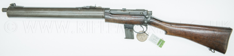
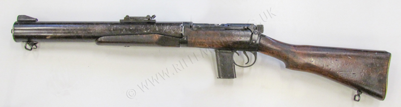
Whilst neither a training weapon nor a small-bore conversion, this arm is nonetheless a noteworthy conversion of a Short Magazine Lee-Enfield Rifle (S.M.L.E.).
It is also unusual in that the conversion entailed an increase in calibre rather than reduction, albeit from the .303-inch centre-fire rifle round to the .45- calibre Colt Automatic pistol round.
Apart from it being a conversion of the S.M.L.E., a further justification for inclusion of this full-bore service weapon, within our training and miniature-calibre remit, is that De Lisle's original concept, from which the commando carbine was developed, involved his prior personal adaptation of the ubiquitous lightweight Browning sporting semi-auto rifle.
This .22 silenced carbine is specifically covered on page linked below.
The De Lisle "prototype" silenced carbine in .22RF calibre
The .45ACP carbine design was conceived at Dagenham (the Essex home of the Ford Motor Company) by William G. De Lisle and Sir Malcolm Campbell (famous World Land and Water Speed record contender and holder, and father of Sir Donald Campbell) specifically for covert operations, such as those organised by the British Special Operations Executive (SOE).
Trials of this carbine were undertaken in 1943, and De Lisle had successfully applied for a patent, number 579,168 issued on 8th. May 1943, for the specific design of the silencer, and although the principle of a baffled silencing system had been used by Hiram Maxim many years earlier, the particulars of De Lisle's design brought significant advances to the genre.
In fact, the details of De Lisle's patent remained secret and unpublished until post-war when he requested permission to have them applied for and published initially in the U.S.A and U.S.S.R. (the Soviet Socialist Republic of Russia).
 This patent, of the same date as the complete version for the .45 calibre Lee-Enfield conversion, was an abridgement relating only to the silencer design.
In a letter De Lisle wrote to the Ministry of Supply at Adelphi House in September of 1943 he refers to both his patent for the .45 calibre carbine and that for his .22RF model previously applied for. It is possible that it is to this abridged version he referred, as we have yet to find a specific application that would have covered his personal .22RF semi-automatic carbine.
In that letter (see the onsite Public Records Office archive documents pages 55 and 56), De Lisle also referred to his designs for a .22RF machine gun that could feed ca. 1,000 rounds per minute, and which gun weighed no more than the silenced Sten sub-machine gun, as well as a silenced 9mm Parabellum machine gun and a recommendation for possible military use of his own .22RF silenced carbine. He advise that he could produce a .22RF replication of most service machine guns for training purposes.
Click image for PRO documents

The assembly of the .45" calibre silenced commando weapon was a fastidious task involving the careful choice of tolerances between parts and small but critical modifications to render the action as quiet as possible in operation. Even the underside of the bolt handle had a dovetailed recess machined to accommodate a rubber, leather or synthetic pad which prevented the customary Lee-Enfield loud 'clunk' given by the striking of the handle against the butt-socket when the bolt was closed quickly.
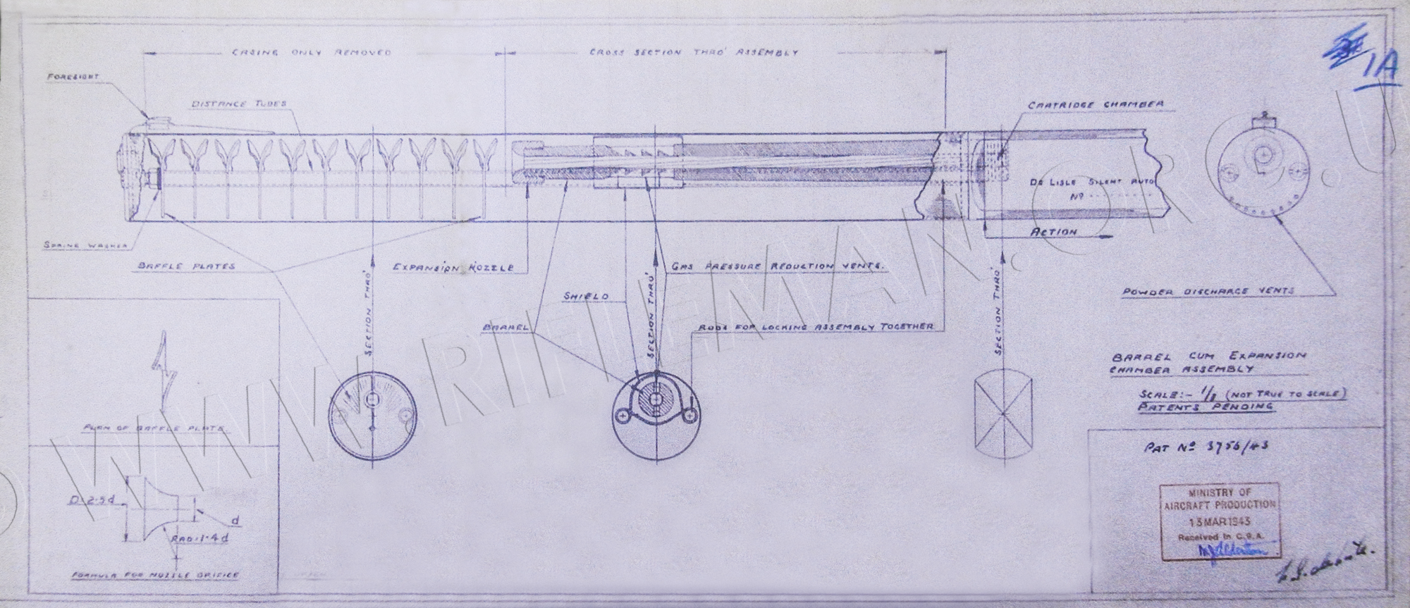
An early drawing of the silencing system was produced in March 1943 by the Ministry of Aircraft Production, with whom De Lisle was then working.
Hover over or Click image to bring up hi-res file and magnifier
Being largely De Lisle's project, the carbine was prototyped by his team at Dagenham and subsequently manufactured, by Sterling Armament, in numbers probably rather less than the originally contracted figure of five hundred; it has been suggested that as few as 120 were forthcoming, although eventual serial numbers in the low two-hundreds are in evidence. The early prototype models used a steel moderator casing, which was given a phosphated finish. Sterling production utilized a blacked alloy casing.
 Right: a letter between the Armaments Design Department at Cheshunt and the Sterling Engineering Co., at Dagenham, Essex, dated mid-November 1944, noting the diversion of two De Lisle units from the existing contract for 500 carbines, and cancellation of further supplies of "these stores" at no cost to the department.
Image by courtesy of the Pattern Room Library now resident at the Royal Armouries Museum, Leeds.
Around mid 1943, the carbine was compared with a silenced version of that famous and reliable sub-machine gun - the Sten. The De Lisle product was, however, initially deemed not to be as quiet as the Sten equivalent although, by early 1944, a further trial of two submitted carbines gave rise to an appraisal which stated that "the guns appeared to be less noisy than the Sten [Mk.II (S)] and gave a smaller group [5 rounds], the best group being 1¾" x 1" at 20 yards, as against the best Sten group of 4" x 2½" at 20 yards." Large batches of ammunition were fired through both the Sten and the De Lisle, with one run of 5,000 rounds proving that, whilst heavy coking of the baffles with powder residue caused silencer disassembly difficulty, and cleaning was required after a very few hundred rounds had been put through the weapon, the system of solid offset baffling through a comparatively large volume gas containment tube, where the bullet suffered no physical contact with any part of the suppression components, worked considerably better than some had expected.
The conversion consisted of removal of the .303 calibre rifle barrel and magazine followed by replacement with a bell-mouthed modified .45 calibre Thompson sub-machine gun barrel and modification of the magazine-way to accommodate a .45 auto pistol magazine from the Colt 1911 model. The final addition of one of the most efficient moderating systems ever devised, resulted in a short and silent arm considered to be effective beyond expectation. The manner in which, on many of the carbines, the bolt was shortened and the breech-end of the barrel brought rearwards into the original .303 receiver of the S.M.L.E. No.1 being converted, is reminiscent of the configuration of the post-war training and target Enfield Rifle No.8. in .22RF.
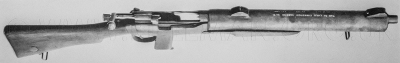
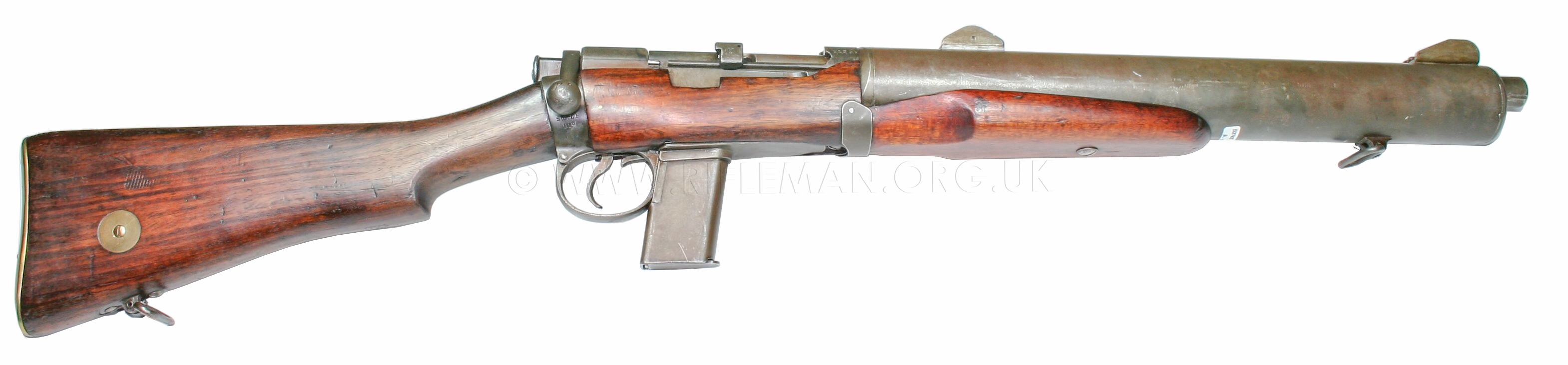
Original testing included trials with a down-loaded .303 cartridge, possibly loaded with pistol type bullet-heads, and a 9 mm Parabellum round as well as the finally selected Colt .45 Auto cartridge, which was proven to have "the most suitable ballistics" and "the best residual striking energy". Several prototype carbines were constructed with phosphated steel silencer bodies, prior to the adoption of the weight-saving aluminium version finally put into production with Sterling Armament. An example of the early prototype held in the Pattern Room is shown below. This prototype was not yet fitted with the rubber bolt-closing quitening pad eventually added into a machined dovetail in the underside of the bolt handle. The aforementioned pad prevented the notably audible metallic clonk, familiar to the firer of any Lee-Enfield, made as the bolt handle connected with the receiver body socket as the bolt was closed. These inserts are found in a number of different materials, including wood, rubber and bakelite.
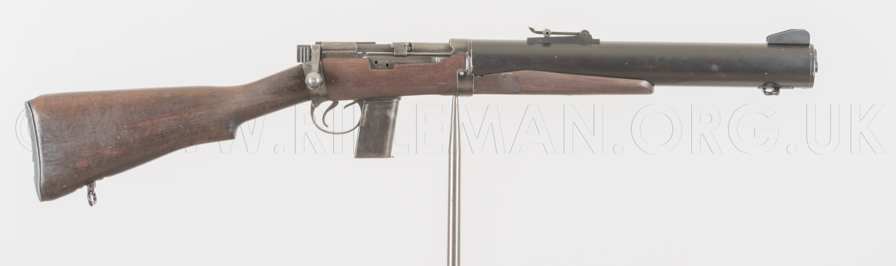
The quite basic fabricated sights fitted to this prototype may have been "in-house" manufactured, rather than the Lanchester sub-machine-gun rear-sights which were used on the production De Lisle silenced carbine. The rear-sight is, though, akin to those seen on cheap air and small-bore sporting rifles of the day.
Images of this prototype carbine are by courtesy of the Trustees of the ex. Pattern Room Collection, now at the Leeds Royal Armouries National Firearms Centre collection
Note that the two holes in the right-hand side of the S.M.L.E receiver, which were for the fastening of the now removed charger bridge, have been filled.
This nicety was dispensed with in most of the later conversions, probably in the rush to get the first carbines into use. Indeed, no attempt ever seems to have been made even to fill in the cut-out in the remaining fore-end woodwork that once accommodated the bridge.

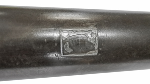
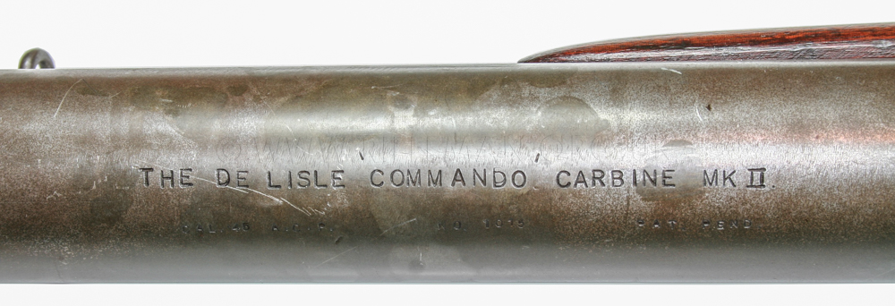
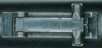
The phosphated steel moderator tube was engraved with the text, in prominent capitals,
" THE DE LISLE 'COMMANDO' CARBINE"
stating clearly the weapon's intended purpose, and adding calibre and the pending patent details
" CAL. .45 ACP NO.1010 PAT. PEND. "
The serial numbering was probably, as is commonly done, commenced with 1,000, suggesting the carbine to actually be prototype number ten.

This engraving has, perhaps rather ostentatiously, been added to many of the latter-day replications of the carbine, even those purporting to be production models.
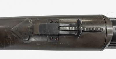
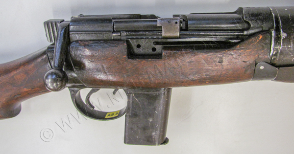
Below: the action from above, illustrating the rearward extension of the .45 barrel into the SMLE receiver, and the associated shortening of the bolt body to compensate.
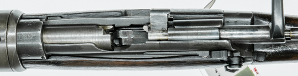
That the parent Lee-Enfield rifle has seen some consderable service is evidenced by the various marks.
After its initial life in the military, and quite possibly after a period of service in the Great War (WW1), the rifle was eventually declared suitable for only emergency use, and thus marked " EY " on the receiver ring.
When no longer suitable for even such use, the tired old thing was relegated to drill practice only, and the " EY " was barred-out and over-stamped " DP " (Drill Purpose)..

It will later be seen that the rifle was destined to be sold off, and was stamped with the opposing 'broad arrow' mark to indicate that.
Whether the arm was actually sold and recovered from a civilian home for the conversion, or whether the sale had yet to take place and the rifle was found from within military stores is not known.
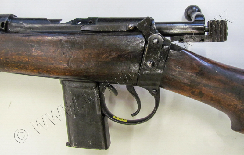
Below: the action viewed from the right-hand-side.
The filling-in of the charger-bridge mounting holes can be more clearly seen, as can the extension of the .45 ACP magazine-well through the trigger-guard's .303 well blanking-plate.
This must be one of the earliest modified Colt .45 ACP magazines, showing the brazed-on rear spine that locates in the groove at the rear of the original .303 magazine-well.


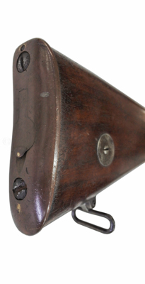
At this point in development, the butt-plate
was still the original brass unit of the parent rifle.
The butt disc is unmarked.
The action used is from a 1910 Enfield-made S.M.L.E. Mark III.
Note that a rear sling loop is still on the toe of the butt.
The bolt closing quietening pad, later to be dovetailed into the underside of the bolt-handle has yet to be added.
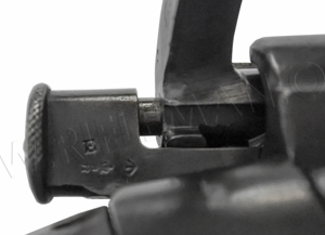
Below: the early SMLE button type cocking-piece, Enfield made, and carrying its inspection mark and "Broad Arrow", indicates that possibly even the original bolt of this 1910 SMLE was utilised.
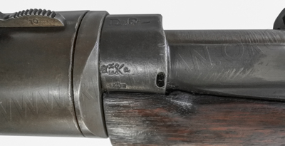

The LHS of the receiver ring carries the original inspector's marks, while the RHS has the original serial number "M 541"
The two juxstaposed 'broad arrows' indicated that the rifle had been "Sold out of Service".
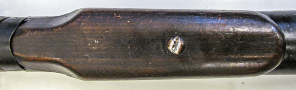
Below: the underside of the moderator and its back-plate mounted to the front of the SMLE action body. The front of the modified trigger-guard unit, with its integral .45 ACP magazine-well just out of shot to the left.
On the production weapons, this area was hidden by the walnut hand-hold that was deemed necessary, and fastened into a captive nut fixed inside the bottom of the moderator tube a few inches forward of the back-plate, with a curved flat steel strip covering the join.
That such a component has yet to be added at this time is shown by the lack of fixing holes in the wood, either side of the barrel bedding king-screw, for this later cover-plate.

The back-plate flange, up to which the moderator tube is butted, is also rather thicker than that eventually fitted to the production weapon.
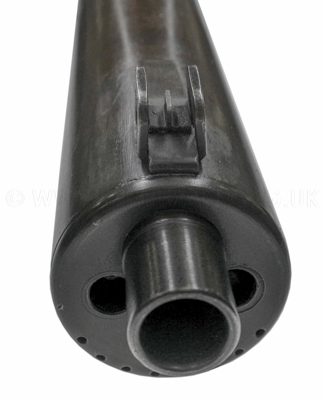
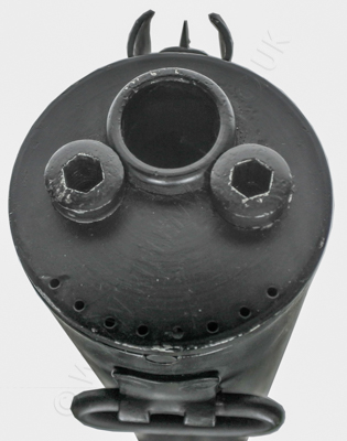
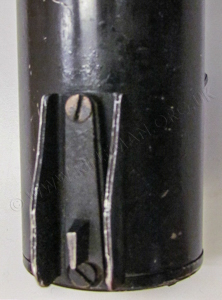
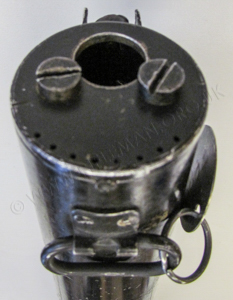
Below: the moderator tube's steel front plate with the muzzle extension, later much reduced in prominence, and the gas vent holes; also shown is the fore-sight arrangement.
The prototype weapon is missing the female threaded barrel-bolts that hold the moderator to its two long support rods that are screwed into the back-plate attached to the front of the action body. It is therefore unknown whether, at this point in development, these were of the 'Allen' hex-cap-head type, or had just plain slotted machine-screw heads.
The former were most usually found on Sterling Armament Co. production, but some refurbished weapons were later, probably post-war, fitted with slotted barrel-screws holding their alloy moderator tubes.
 ....
....  .....
..... 
On the 'Pattern Room' carbine, the front sling-swivel attachments must originally have been just soft-soldered to the underside of the steel moderator tube, and were evidently more mock-ups than attachments intended for service use, as they long ago departed from their positions.

 Left: the front attachment point.
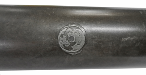
Right: the rearmost attachment position.
__________
Below: the fabricated fore-sight and ramp viewed from above.

The hand fabricated rear-sight appears to be a cannibalisation of a common .22 rifle version,
such as that from one of the BSA Sportsman models, to which a larger heart-shaped mounting plate has been welded,
and over which a spring-loaded keeper has been formed and screwed to the moderator-tube.
However, oddly, the BSA sporting rifles, on which this type of rear-sight was usually first used, were not introduced until after the Second World War, around 1947.
This raises a question about which was first; had the sight been designed pre-war but not retailed at that point, with an in-the-know individual borrowing a prototype?
It seems unlikely that BSA's design was copied from the De Lisle, as this example appears to have been borrowed from elsewhere. In the event, this sight was probably deemed too lightly constructed and easily disturbed for the weapon's intended purpose, and other gun sights were considered during later trialling; the final option being the Lanchester type.
A photograph of one carbine in Major E.G.B. Reynolds' fine1960 reference book, "The Lee-Enfield Rifle", shows one of the prototype carbines, engraved in the same way as the example covered here, but with a rear-sight taken from a Mk.1* model of Lanchester sub-machine gun introduced in 1942.
A similar prototype carbine was once in the collection of a Southern England based dealer. This was understood to be serial number "17", also with the moderator tube engraved.
Hover over or Click image to bring up hi-res file and magnifier
The latter two prototypes are interestingly designated as "Mk.II", perhaps as they are fitted with the Mk.I Lanchester rear-sight rather than the early fabricated type. They each have the phosphated steel moderator tube of these early models.
The word COMMANDO has been the given the benefit of single quotation marks, and the patent pending mark "PAT. PEND."is beneath the right-hand end of the main text. De Lisle was not afforded permission to publicly seek a patent for his design until post-war.
_________________
The next two images of a standard issue carbine can be rotated and zoomed,
either as initially loaded or full-screen for higher definition.
Slide cursor < > to rotate, and Click to zoom.

The carbine in the above image is fitted with the extended magazine discussed further down the page.
Technical specifications of the three De Lisle carbine types |
|||
PROTOTYPE |
AS ISSUED |
AIRBORNE MODEL |
|
| Cartridge : | .45 Colt Auto |
.45 Colt Auto |
.45 Colt Auto |
| Muzzle Velocity : | 830 ft/sec |
830 ft/sec |
830 ft/sec |
| Effective Range : | 275 yds |
275 yds |
275 yds |
| Length - Overall : | 37.2 inches |
35.3 inches |
25.7" folded - 35.3" extended |
| Length - Barrel : | 7.25 inches |
7.25 inches |
7.25 inches |
Furniture : |
Walnut |
Walnut |
Walnut |
Rifling - No. of Grooves : |
6 |
6 |
6 |
| Rifling - Twist & Direction: | 1 turn in 16" - RH uniform |
1 turn in 16" - RH uniform |
1 turn in 16" - RH uniform |
| Sight - Fore : | Fabricated protected windage adjustable blade |
Fabricated protected windage adjustable post |
Fabricated protected windage adjustable post |
| Sight - Rear : | Mk.1 Lanchester |
Mk.II Lanchester |
Mk.II Lanchester |
| Sight - Radius : | 13.6 inches |
12.25 inches |
12.25 inches |
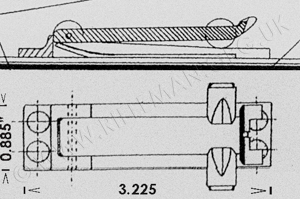
Below are two outline and sectioned drawings associated with the specification for the SMLE based .45 calibre de Lisle carbine and its patent.
These will be seen to show a carbine with the protruding muzzle boss of the prototype arm, the under-moderator walnut hand-hold, and what appears to be the tangent-leaf rear-sight from an SMLE located at the very rear of the moderator.
The spiralled split discs forming the moderator baffles are shown, as is the "gas unnel" designed to spread out and slow the propellant gases, expelled from the internal barrel's muzzle, before they pass through the baffles.
These drawings precede those shown in the patent application shown near the bottom of this page.
Those later drawings show the addition of a sleeve over the forward part of the barrel. This sleeve is affixed to a thread on the muzzle of the barrel, and therefore closed off at the forward end. The sleeve has a clearance gap, between itself and the barrel, that takes propellant gasses from a matrix of staggered bleed holes around the barrel, centred about an inch behind the crown.
These gases, bled from behind the departing bullet, are sent rearwards to the open end of the sleeve, where they hit the moderator's back-plate and are bounced forward between the outside wall of the sleeve and the interior wall of the moderator tube, then continuing forward through the baffles to exit the vent holes in the moderator's front plate, and, of course, the false muzzle boss in that plate.
On Sterling production models, the alloy interior of the muzzle tube was protected from erosion by the hot gasses with a thin rolled brass shim fitted tightly inside the moderator casing, for its length between the back-plate and the first baffle.
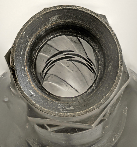
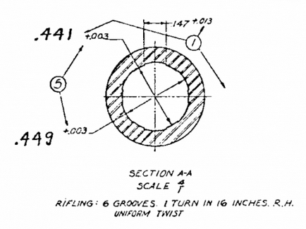
The section of the drawing for the Thompson sub-machine gun showing the rifling.
An apocryphal tale of one trial of the first De Lisle prototype is that the urgently required new weapon was completed overnight and taken to the London building of the Special Operations Executive (S.O.E.) first thing the following morning. Impatient to discover its capabilities, it was test-fired at pigeons on the roof of a building opposite. So quiet was the report, in the early part of the wartime "rush hour", that there was no reaction from passers-by. How the pigeons reacted was not reported; and neither is there any indication of concern for the fall of shot.
One should perhaps remember that significant quantities of metal of all types were then falling from the skies over England, and the odd .45 calibre pistol round, on a decaying trajectory, even had it been spotted, may barely have raised an eyebrow. Health and safety considerations were at the time hardly in the fore-front of general thinking. Allegedly, the carbine was immediately despatched to the continent for further assessment (perhaps even a practical trial), and further examples ordered on the spot.
However, as with many such anecdotes, whilst there is an element of truth in the above story, the veracious, and only marginally less thought-provoking version, came from the horse's mouth. Interviewed by Mr. Ian Skennerton in 1981, William de Lisle related how, during early "field-testing" of the suppressed carbines, they were fired at a large chimney across the road from the Wilkes gunmaker's premises near Piccadilly where prototyping was taking place*. The discharges were thereby proven to be "imperceptible" to those passing in the street below; the possibility of heavy hail notwithstanding!
A more recent confirmation of Wilkes' involvement with the De Lisle carbine
illustrates that the company's work was highly significant.
The business was engineering prototypes for such a the "Remote Control Gun" - a belt-carried concealed Colt 1903 semi-automatic pistol operated by a thin Morse-type cable run down the coat sleeve - which work was amongst that undertaken for the Special Operations Executive (S.O.E.)
De Lisle himself, and Sir Malcolm Cambell were apparently frequent visitors to the Wilkes London Gunshop, where some of the machining was done for De Lisle's various projects.
More detail of the Wilkes Gunmakers' significant wartime activities can be found HERE
A chapter and verse section on the conception and production of the carbine is to be found contained in a contemporary report also covering the Patchett machine carbine and other silenced weapons of the time. The document is held in the National Army Museum's archive. We reproduce it here verbatim.
DE LISLE COMMANDO CARBINE
Not a War Office order, but ordered for Combined Operations through Major Sir Malcolm Campbell, to models designed by d.G. de Lisle.
1943 order for 500 carbines – Sterling Engineering Co./ Dagenham 6.10.44. Order for 2 more for Ordnance Board Trials – cancelled 16.11.44.
Ordnance Board proceedings list that the contract for 500 was terminated at 106 carbines. Proposed production of 50 Airborne models, included in the 500 order was also cancelled. Ord. B. remarks 20.12.45
DE LISLE COMMANDO CARBINE
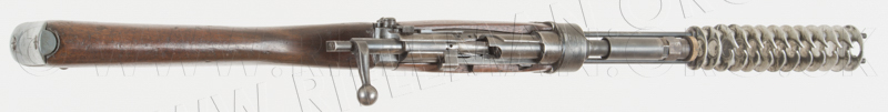
Invented by William Godfray de Lisle, who was working for the Ministry of Aircraft Production, during the war. His first prototype was a .22 Browning
self loading rifle, which he modified and restocked, and was built in Beckenham in 1942-43. This rifle was mainly used for "quietly despatching small game on the Berkshire Downs, for the table at a time when meat was in short supply.
This prototype rifle is fitted with a 1st War vintage Periscopic Prism Co. telescope on overhead ring mounts.
Major Sir Malcolm Campbell came to hear of de Lisle and his rifle and inquired
of its effectiveness, so it was brought to London and fired from the top of
the Adelphi building into the Thames, and considered worthy of further development. Campbell asked for a 9mm model to be built up, which de Lisle did, but in reducing the velocity of the 9mm projectile by venting the barrel, problems arose with shavings from the projectile, and de Lisle considered that it lacked the desirable stopping power, recommended the .45 ACP round.
A prototype .45 de Lisle was assembled using an unserviceable No.1 action, at Bapty Co. workshop, and forwarded to Campbell for testing. It was found to have nil flash at night, and to be inaudible over 50 yards and non-typical of the sound of a firearm discharging. Campbell ordered a small batch for testing and use in clearing operations on the occupied French coast, as Campbell was with Combined Operations and involved in French coastal raids and clearance operations.
De Lisle, who was a personal friend of Major Holland, wanted to make the carbines at Hollands, but Campbell instructed that they be built at the Ford Dagenham
plant, of which he was a director. Seventeen carbines were built up there, with
the assistance of a factory foreman, machining being done in the tool room, and assembly being carried out in the manager's ARP dugout. These carbines are sliqhtly different to the later production run, as they have a steel silencer jacket which has been phosphated, simple siqhts, and smaller serial numbers are stamped on the top of the silencer jacket, and range from 1002 to 10153. "DE LISLE CARBINE" is also stamped along the top of the jacket. These carbines were put straight into service with commandos and used for silencinq sentries.
Combined Operations then ordered a production run of 500 carbines, from Sterling at Dagenham in 1943. Unserviceable S.M.LE. rifles were converted, and .45 barrels supplied by Greeners in Birmingham. It is most likely that these were converted Thompson barrels. It was proposed to make 450 Commando carbines (desiqnated Mk.II as the triaIs batch of 17 were designated Mk.I) and 50 Airborne model which had folding butts slmilar to the early Patchett Carbine These were to be serial numbered 451-500.
These orders were separate from the normal service orders, and the Ordnance placed an order with Sterling for 2 carbines for trials. This order was cancelled as two were drawn from production. The order is recorded as having been terminated at 106 carbines, and only one prototype airborne made, at Sterling. Although some troubles were encountered with the projectile striking baffles (de Lisle claims this was due to the positioning rods being slackened off, against his advice) the de Lisle performed favourably against the silenccd Mk.II Sten, and the WelI siIenced Sten. Accuracy was quite qood, except when the baffIes were damaged.
The Sterling made de Lisle carbines have duralium baffles and an alloy silencer casing, with a sight graduated to 200 yds. It is likely that the sight was by a sub contractor. Serial numbers on these carbines are found on the receiver at the point where the charqer bridqe was removed, and appear to range up to about 130. After the war, some were reconditioned at Enfield and used in Malaya. They were also used quite successfully against the Japanese in Burma ..
De Lisle's .22 carbine is covered in detail HERE
It is worthy of note that, whilst the telescopic sight of De Lisle's .22 carbine is quoted in the above record as being of Periscope Prism Company manufacture, the 'scope actually mounted on the carbine was in fact a German Helios No.3 model made by the Fuess company of Steglitz. It may at the time have been considered politic to reference the telescope as being British made.
By courtesy of the Royal Armouries we are able to show the contemporary documents relating to the investigaton and cancellation of production of the carbine.
This can be viewed as a text-searchable flip-page document
or with vertical scrolling by clicking the portrait icon.
Depending upon the number of pages it may take a few moments to load.
Double tap tablet or click ![]() for full page display.
for full page display.
Eventually, De Lisle's silencing design evolved to be almost as quiet as the equivalently purposed "Welrod" silenced pistol of either .32ACP or 9mm calibre, although that very specialist side-arm held only very short range capability and utilised rubber and textile baffles through which the bullet was fired; these required replacement after the firing of but a comparatively few rounds.
The 9mm Welrod pistol with fabricated trigger-guard.
The .32ACP variant was unguarded, simplifying the concealment of the two parts of the pistol when broken into its two components (barrel and butt/magazine).
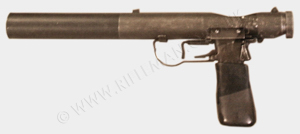
Image by courtesy of the Trustees of the Infantry and Small Arms School Corps (SAS C) Weapons Collection
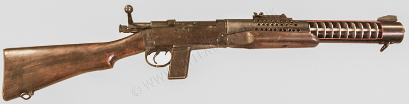
Image by courtesy of the Trustees of the Infantry and Small Arms School Corps (SAS C) Weapons Collection
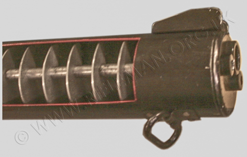
The cutaway moderator illustrates the baffle arrangement. The baffles are supported by two rods horizontally positioned either side of the bore-line (the right hand rod is here visible). The barrel is of the order of 9 inches in length, bell-mouthed, and is accommodated entirely within the perforated section of the moderator tube immediately in front of the action body. These perforations are simply part of the sectioning permitting internal viewing; they are not to be found on production weapons.The tangent rear-sight fitted is that of the Mk.1 Lanchester
Note that the magazine release-catch is bent lower, and appears to be on the short side.
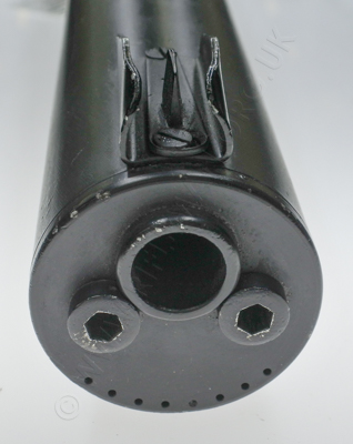
The front plate of the moderator casing shows the screw-in muzzle-ring and Allen-type fastening cap-head female-threaded "barrel-nut" machine-screws that draw the casing tight to the carbine's action via the two internal rods which also support the baffle-plates.
Some examples, such as the Shrivenham collection's carbine shown further down this page, are to be found with plain slotted alloy female barrel-nut fastenings.
The standard capacity seven-round modified Colt 1911A1 Auto magazine could be replaced by various extended versions with capacities rarely up to twenty rounds, but more usually eleven.
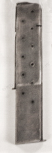
The extended locating rib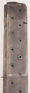
brazed to the rear of the magazine
can be clearly seen, as can the chamfer point
which engages in the
original S.M.L.E. locking/release lug.
The wear witness marks show the point
to which the magazine-well reaches,
and below which the magazine
extension protrudes unsupported.
Images by courtesy of the Trustees of the Infantry and Small Arms School Corps (SAS C) Weapons Collection
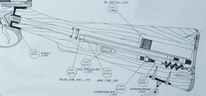
Below is a Sterling sectional drawing of the carbine - dated 1-1-45, of its late-war specification, and listing issue numbers from 1 to 6 recording changes made on dates between the 1st. of January and the 17th. of July 1945.
Click on the image for a high resolution view.

Below: the carbine disassembled as far as is practical for regular maintenance.
The walnut furniture beneath the action body cannot be removed without removing the larger circular "C-ring" type nut that encircles the barrel and holds the cylindrical rear mount for the moderator casing to the front of the action.
Click the image for a high resolution view.
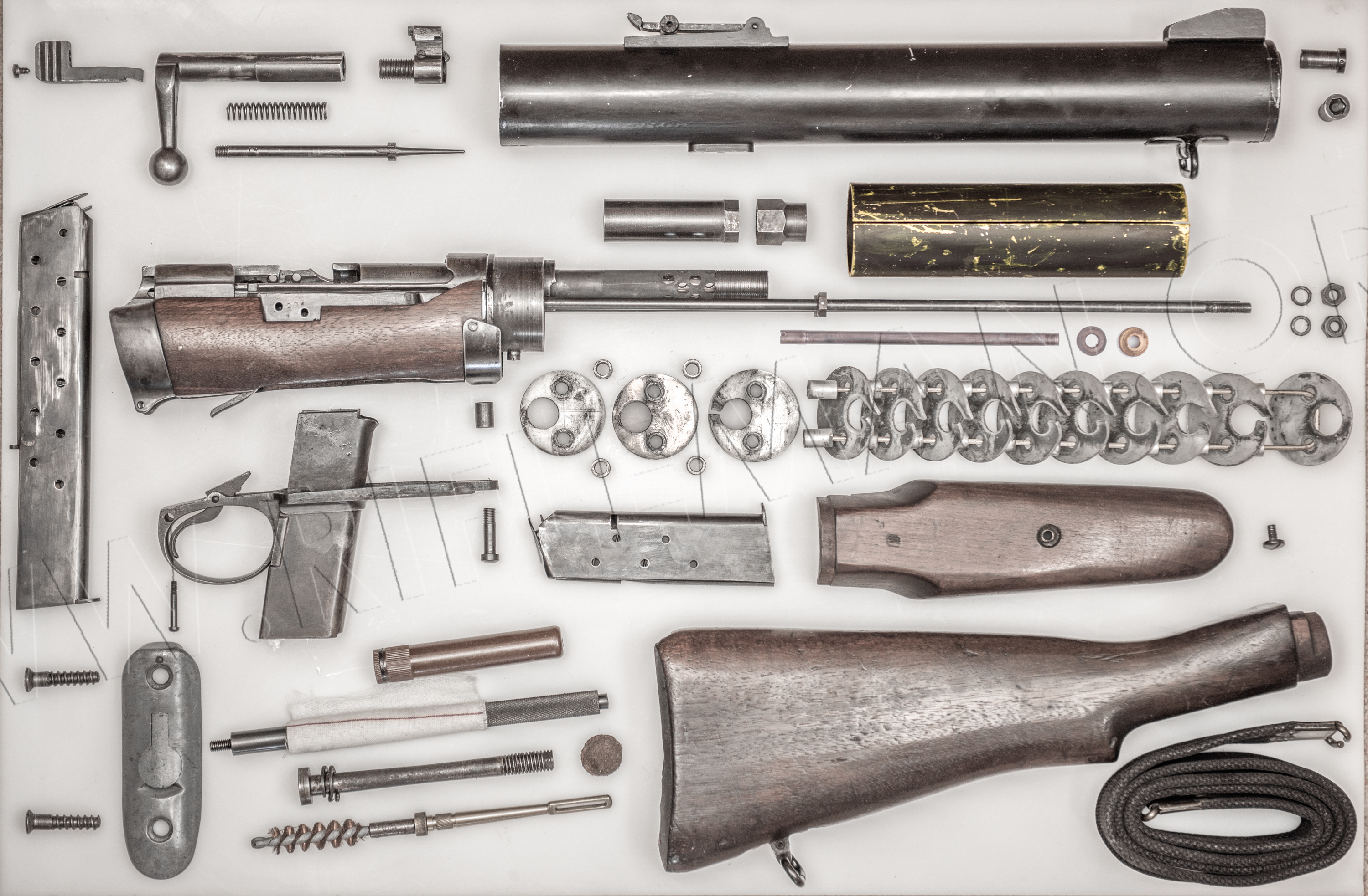
The bulk of the baffle plates are slid onto brass rods simply for ease of display.
N.B. The tube above the baffles in this photograph is the .22RF Aiming Tube adapter barrel, with, to its right, the brass knurled muzzle locking-nut and its leather washer.
This conversion unit is discussed further down the page.
Images of this next Sterling production carbine - serial number 129 - are by courtesy of the Trustees of the ex. Pattern Room Collection, now at the Leeds Royal Armouries National Firearms Centre collection

One little noticed alteration to the prototype and standard issue SMLE rifles, is the lowered and slightly extended magazine release-catch. This was a sensible provision to minimize the small risk of a failure to quickly, quietly and safely change the magazine under difficult circumstances, perhaps under pressure in the dark.
Below: a skeletonised SMLE action, shown to afford comparison between the issue and De Lisle magazine release levers.

The carbine viewed from the left-hand-side.

The prototype weapon shown earlier was not the only example to be engraved on the moderator casing. On the left-hand-side, just ahead of the walnut hand-hold, is the text
" THE DE-LISLE CARBINE "
" C.O.S.D. 2.lll. S.E.C.O."
The initials stand for "Company Ordnance Supply Depot".

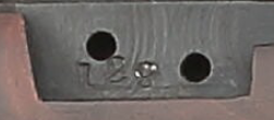
Right: the carbine's serial number is stamped in three places; on the barrel, on the side of the action body, where the woodwork is cut out for the charger guide ...........

Left: the action, showing the later
Lee-Enfield Rifle No.4
type of cocking-piece,
the lower and lengthened magazine release-lever,
and the unfilled holes through which the
parent Lee-Enfield No.1 Rifle's
charger-loading bridge was fastened.
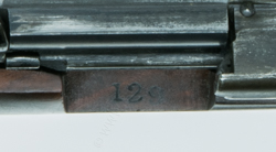
........... and, right, the serial number "129"
is also repeated on the top of the woodwork
where it was cut-out for the charger-bridge.
Below: the 'business' section viewed from above.
Inquisitive readers may be asking why they have spotted a radioactive warning label attached to the carbine in some of the images.
During both World Wars, for night-time operations, a number of weapon sights were treated with radium based luminous paint, of the same type that was also used on watches and compasses, and which is nowadays considered a health hazard, and banned from everyday use. Most of this paint has therefore had to be removed from museum items that once carried it, but labels are still added to warn that there may still be traces present. The museum armourers have a geiger-counter available to ensure such exhibits remain below safe radiation levels.

The magazine with a lanyard loop is probably not correct, being from a .455 calibre Colt 1911 semi-automatic pistol, such as a WW1 Royal Flying Corps aircrew issue sidearm.
The MK.1 Lanchester SMG rear-sight is rivetted to the moderator tube, as the aluminium is too soft and thin to seat machine-screws.
The almost crudely stamped range calibrations are simply for 50, 100, 150 and 200 yards.

..........
This carbine was converted from a 1918 Mk.III SMLE made by the B.S.A. Company.

At some point, probably long after conversion from a Short Lee-Enfield rifle, it underwent a Factory Thorough Repair, denoted by the " F.T.R. " stamp on the butt-socket. Occasionally the FTR stamp is accompanied by a two-digit year date, but sadly not here.
The carbine has been overcoated with the hard and durable Suncorite baked-on matt finish, usually painted over degreased Parkerising or over a bead-blasted and phosphated prepared surface. Suncorite was indeed first introduced in 1944 before the end of the Second World War, but the earliest FTR date we have found thus far is 1949, at the Fazakerly Royal Ordnance Factory.
This would suggest that the earliest the carbine may have been refurbished was at the end of that decade, but the work could have been undertaken many years later, almost up to the time the weapon was transferred to the Enfield Pattern Room from Royal Ordnance PLC, Nottingham, in March 1993, prior to being gifted by the Ministry of Defence to the Royal Armouries with the Pattern Room Collection in August 2005.
 The front sling-swivel is shown, left,
flush-rivetted on below the front-plate;
and the windage adjustable fore-sight, right, above the now stubbier false muzzle, which is threaded into the front-plate.
Barely visible in this photograph, the fibre pad, introduced to quieten the classic metallic 'clunk' of Lee-Enfield bolt closure, and which was dovetailed into the underside of the bolt handle, is only just evident on very close inspection.

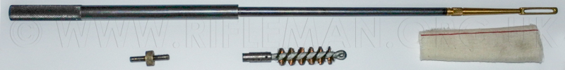
To be found as a component in the Sterling Armament Co. drawing shown earlier on the page, and enlarged below, the illustrated two-part tubular cleaning rod, unseen for many a year, was discovered wrapped in oiled cloth in the butt-trap of this carbine.
The thinner rod, to which the looped brass jag or bronze wire brush would be screwed, stows inside the larger diameter open-ended tube with a knurled end. The jag and brush are screwed onto each end of a threaded keeper that has a knurled brass nut at its centre. An oil-bottle, in this case a bakelite version, can also still be accommodated in the butt-trap. The hole through the butt, by which the stock-bolt is fitted, has been opened out above and below the centre line. The jag/brush unit is stowed in the lower groove, the oil-bottle in the upper groove, and the telescoped cleaning rod slides between them, up to the leather washer that protects the trap's contents from the head of the stock-bolt.

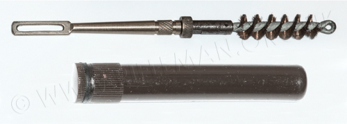
The arrangement is clearly shown in the drawing.
In 1957 the "De Lisle" was reappraised with a view to "its possible use in Malaya".
It was noted then that the carbine "is designed fundamentally as a silent carbine, and is NOT a carbine fitted with a silencer".
The report went on to say that the 'De Lisle' was then considered an ideal weapon for silently dealing with any sentries discovered during jungle patrolling operations. There are certainly reports that the weapon was issued in this theatre, as it was in Korea and indeed Northern Ireland and possibly the Falklands. There have even been claims for the carbine's believed usage in even more recent times, although these are unsubstantiated.
More of the De Lisle "Commando" carbine & Trials documentation
By courtesy of the trustees of the ex. Pattern Room Library, now resident at the Royal Armouries Museum archives, Leeds.
We are able to show contemporary documents relating to trials and decisions made regarding the De Lisle carbine in the latter part of WWII. Included is a March 1944 report of trials including grouping comparisons between the De Lisle silenced carbine, a Welrod silenced weapon, and the silenced Mk.II Sten sub-machine gun.
The size of a ten-round group was noted after each firing of consecutive lots of 500 rounds between commencement and the final 5,000 shot total. The report also covered "coking" of the moderating system of each weapon, and commented on reliability, noting failings and likely operational actions necessary to maintain efficiency.
There is also a later Ordnance Board report on the Endurance Trials report, with appendices. The final document is the one illustrated early in our page, being a letter between the Armaments Design Department at Cheshunt and the Sterling Engineering Co., at Dagenham, Essex, dated mid-November 1944, noting the diversion of two De Lisle units from the existing contract for 500 carbines, and cancellation of further supplies of "these stores" at no cost to the department.
This can be viewed as a text-searchable flip-page document
or with vertical scrolling by clicking the portrait icon.
Depending upon the number of pages it may take a few moments to load.
Double tap tablet or click ![]() for full page display.
for full page display.
For those involved with serious research into British smallarms, a visit to the weapons collection of the Defence Academy at Shrivenham will afford significant reward. We are grateful to the Academy and its highly knowledgeable staff for the opportunity to photograph a number of their exhibits. The following images of their example of the De Lisle Carbine are fully acknowledged as being available entirely by the courtesy of the Academy.
The carbine there on display carries serial number 209, a fairly high figure in the supposed number of carbines believed to have been manufactured. Compared with other examples of the few available for viewing in the various museums and collections in Britain, there are some notable features, which we will mention with the relevant images.
The action is representative of a Sterling Armaments product, but the moderator casing has been replaced and is without the original small stamp-sized plate, impressed with the Company's name, that used to be attached to earlier Sterling produced aluminium casings; which plate is now rarely seen.

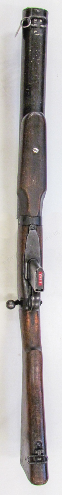 To the left: the upper view of the carbine,
and to the right, the underside, showing the hand-grip
attached with a large, slightly domed plain-slotted aluminium machine screw.
Below: the right-hand side of the S.M.L.E. action, showing the frontal cut point
for the fitment of the adaptor-plate for the modified
Thompson machine-gun barrel and moderator casing.
The photograph well shows the shortening of the bolt body
which was necessary to permit the rearwards
intrusion of the .45 calibre barrel into the S.M.L.E. receiver.
It should be noted that the magazine follower has been lightly radiussed downwards both front and rear, presumably to reduce the possibility for snagging of cartridges on feeding, and of fired cases on extraction.

The carbine's serial number is also stamped on the section of the fore-end woodwork that once formed the cut-out for the base of the charger-bridge on the parent S.M.L.E. from which the De Lisle was converted.

Above: the relieved S.M.L.E. bolt-head, which takes the .45ACP calibre (Automatic Colt Pistol) round case-head, and its modified extractor.
Below: the fabricated magazine-well plate and magazine-way that is brazed to an original S.M.L.E. trigger-guard unit. The construction and appearance of this component is often an external give-away of a replica of the De Lisle carbine.

A close-up shot of the hand-guard, or rather hand-grip.
That on the Shrivenham carbine is fastened to the moderator casing with an alloy screw that shows considerable signs of distress. Such a fitment may perhaps be considered a step too far in weight-saving.
The Lanchester Mk.II rear-sight is rivetted to the casing with four alloy flush rivets.


The base has the lettters "CFM" stamped in front of the rear pair of rivets, and the serial number "289" is stamped under the tangent leaf. This number inexplicably varies from the serial number "209" stamped on the .45 calibre barrel within the receiver, on the receiver RHS within the cut-out in the woodwork that onece accommodated the charger bridge, and on the upper face of the wood in that cut-out.
The front ring of the receiver is itself stamped with serial numbers probably related to the parent rifle's serial number, and which have been overstamped several times rendering the remaining marking practically irrelevant.
Below: a drawing of the Lanchester rear-sight.

 The foresight is especially made for the carbine, and consists of a simple pressed channel base
incorporating protector wings, and a crude but no doubt effective
windage/zero adjustable tapered blade on a rear-pivoting flat base-plate.
The front sling-loop is the classic Lee-Enfield part, held in another purpose-made pressing from a piece of flat sheet which is flush-rivetted to the underside of the moderator casing.
The front end-plate to the moderator is similar to the early production models, and may indeed be one of those that has had the screw-in "muzzle"-ring removed and the thread drilled out. The front screws have been changed from the designed allen cap-heads shown in Sterling's drawings and usually fitted, to replacement straight-slotted machine-screws; presumably for easier field-maintenance. The plate has the usual eight small holes drilled around its lower periphery. These are described by De Lisle in his Patent Specification (copied in its entirety at the bottom of this page) as allowing propellant residue to be blown from the moderator, rendering it "self-cleaning". This was somewhat wishful thinking, but must have contributed to the prevention of build-up of residue to some extent. The notes on the trials between De Lisle's carbine, the silenced Sten SMG and the Wel silencer (also shown elsewhere on this page), give precise details of the performance of each unit in this respect.
If proof were needed of the efficiency of De Lisle's moderator design and the carbine itself, a December 1950 report, on the potential performance and practicality of the use of the silenced carbine in the Malayan Emergency, stated that an audience of officers, at a talk on the subject given in the open at the FARLEF (Far Eastern Land Forces) Training Centre in Singapore, failed during the lecture to notice that five rounds had been fired from a De Lisle carbine within fifty metres of the audience, not one of whom was aware that a rifle of any kind had been fired.
Details of this report, and many other associated documents from the Public Rcords Office can be read on-site here .......
(PRO) document archive for the De Lisle carbine.
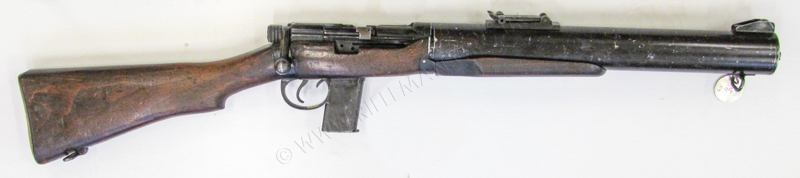
Possibly two prototype, variant models were made of a folding-stock air-portable design. This weapon was never put into even small-scale production.
The only known example in the U.K., shown below, now resides at Warminster.

Above image by courtesy of the Trustees of the Infantry and Small Arms School Corps (SAS C) Weapons Collection
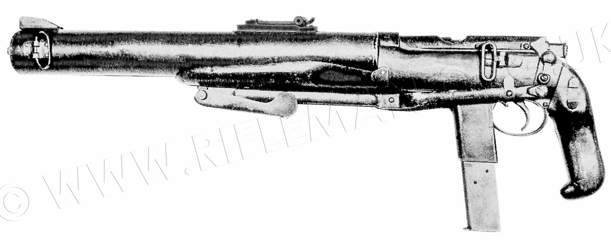
The airportable carbine folded - viewed from the LHS
Image reprocessed from the "Gung-Ho" magazine article of 1984
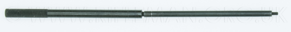
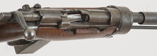
An unusual conversion unit was developed for the De Lisle carbine, in the form of an Aiming-Tube-like adapter in .22 rimfire calibre for small-bore range practice with miniature range targetry.

The self-contained kit comprises the adapter tube and knurled brass/bronze locking nut, replacement .22RF bolt-head, firing-pin, striker and matching cocking-piece, plus an allen/turn-key tool, and tool for unscrewing and switching the .45 calibre firing-pin/striker for the flat-faced striker for the free-floating offset .22 firing-pin in the .22 bolt-head. The allen-key is for the moderator's front-plate machine-screws - as the moderator casing must be removed to fit the brass locking nut to the threaded muzzle of the adapter tube after it has been slid into the parent barrel from the breech. The turn-key end is for the striker removal tool. The barrel sleeve system is practically identical with that utilised for all British Service Rifles from the Martini-Henry's .297/.230" centre-fire Morris Tube to the .22RF Aiming Tubes for all marks of the bolt-action Long and Short Lee-Enfields.
With the bolt removed, the aiming tube slides through the bolt-way into the barrel.
The threaded muzzle of the tube protrudes from the muzzle of the .45 ACP calibre barrel, and the knurled circular nut is fitted, with a thick leather washer behind it, and screwed up lightly, ensuring that, with the bolt back in place, the extractor slot aligns accurately with the extractor lever on the .22 bolt-head, after which the knurled brass nut can be fully finger-tightened.
............... 
A .45 ACP magazine is used that has been fitted with a spring-loaded single-shot loading platform. The bolt head has been chamfered, at its base, to lead smoothly over the loading-platform, at the same time depressing it into the magazine as the bolt is closed.
This arrangement closely follows that used, first decades earlier, when the Lee-Enfield RF Short Mks. I & II rifles could be fitted with the Hiscock-Parker magazine, and again in 1945 when the .22RF Lee-Enfield No.5 trials rifle was made by BSA.
The leather washer and knurled nut can just be fitted with only the moderator casing slid off the carbine. It is not necessary to disturb the baffle plates, which require considerable care in setting up with all their tubular spacers.

.................... 
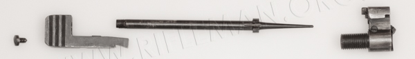
The component parts of the conversion unit are shown below.
From the top: the .22RF barrel with its .45 ACP chamber section to the left, and threaded muzzle for the the brass locking nut with its leather washer to the right. Beneath those are the striker spring, and the striker for the free-floating firing-pin. This striker is modified simply by removal of the firing-pin section from a standard .303 inch CF striker.
The face of the notched flange which both centralises the striker within the bolt, and that provides for the tube-spanner with which it is screwed into the cocking-piece against the tension of the spring, is ground flat to face up to the rear of the replacement free-floating firing pin. The .22RF firing-pin slides within the .22 No.2 bolt-haed with its offset firing-pin hole.
The otherwise standard .45ACP magazine has been fitted with a spring-loaded loading-platform in place of the .45 rounds follower. The platform forms a curved channel to ease single-loading.
The cocking-piece of the .45 bolt needs to be replaced with the one provided in the adapter kit, as this is matched with the shortened striker.
The two items on the lower right of the photograph are the tube-spanner for screwing the striker into the cocking-piece, and the large Allen key that both acts as a turn-key for the locking-screw that locks the threaded section of the striker into the correct postion in the cocking-piece, and for turning the tube spanner within the bolt body. It obviously also provides the key for the necessary removal of the allen barrel-nuts that hold the front-plate and the moderator-casing onto the carbine.
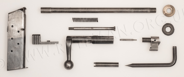
The .45ACP (.303") cocking-piece, striker/firing-pin and centre-fire bolt-head are shown for comparison.
As already mentioned, this adapter kit operates in almost precisely the same way as did the conversions of most of the Lee-Enfield training rifles, from the "Long" Lee models, through the converted SMLE short rifle versions, up to the last of the type, the .22 "No.9" (N.9) Naval training conversion of the Rifle No.4.
The configuration was also similar to that which formed the basis of most .22RF Aiming Tube adapter units for the various bolt-action rifles over decades.
Hereafter, the complete Patent Specification accepted by the Patent Office for De Lisle's application made on the 8th. of May 1943.
PATENT SPECIFICATION
 Application Date: May 8, 1943. No. 3756/43. 579.168
„ „ May 19, 1943. No. 7964/43.
One Complete Specification Left (Under Section 16 of the Patents and Designs Acts, 1907 to 1942): June 7, 1944.
Specification Accepted: July 25, 1946.
PROVISIONAL SPECIFICATION
No. 3756 A.D. 1943.
Improvements in or relating to Means for Silencing Firearms
I, WILLIAM GODFRAY DE LISLE, a British Subject, of The Holt, South Eden Park Road, Beckenham, Kent, do hereby declare the nature of this invention to be as follows:—
This invention relates to means for silencing fireams of the type (hereinafter referred to as the type described) comprising a tubular casing that is carried or is to be carried by the firearm in spaced relation with the barrel thereof, and a plurality of baffle-plates mounted in spaced relation one with another within the casing, which baffle-plates have perforations providing a through-way for the projectile in line with the central longitudinal axis of the barrel.
It is an object of the present invention to provide improved silencing means of the type described of robust and compact construction. which shall be more efficient in operation and more effective in silencing firearms than those proposed heretofore.
According to a feature of the invention, there is provided a method of silencing firearms comprising the steps of causing the gas as it escapes from the muzzle of the barrel to flow in a direction lying transversely of the central longitudinal axis of the barrel, and thereafter to swirl in a confined space situated in front of the barrel with the vortex of swirling offset from the path of flight of the projectile.
Provision is preferably made for reducing the gas pressure behind the projectile just before it leaves the barrel.
Provision is also preferably made for some gas to escape through the wall of the barrel into an expansion chamber that surrounds the barrel and is in open relation with said confined space in front of the barrel for the purpose of assisting in building up back pressure in. front of the muzzle.
According to another feature of the invention there is provided silencing means of the type described comprising the combination of means for preventing or tending to prevent the formation of a partial vacuum at the muzzle of the barrel, with baffle-plates which are so constructed and arranged as to cause the gases emitted from the barrel to swirl about a vortex that is offset from the path of the projectile through the baffle-plates.
The casing preferably extends rearwardly around the barrel beyond the muzzle thereof to provide an expansion chamber situated between the muzzle and the breech of the barrel.
The vacuum-prevention means may be constituted by a nozzle, such as an expansion nozzle, situated or arranged to be situated at the muzzle of the barrel. In some cases this nozzle may be formed or provided on the muzzle.
In a convenient construction a baffle-plate has the form of a disc that has an eccentric perforation for the passage of the projectile, and has a radial slit that extends from the periphery of the discs preferably through the perforation, the two portions of which disc at opposite sides of the slit are spaced apart angularly one in relation to the other in the direction of length of the casing.
The baffle-plates may be each of spiral or substantially spiral formation, and their peripheries may be spaced away from the internal periphery of the casing to provide an annular space or gap that surrounds the baffle-plates at the inner face of the casing.
According to one method of carrying the invention into practice which will now be described by way of example with reference to silencing the discharge of a rifle of .22 in. calibre, silencing means comprises a tubular casing about 13 in. long mounted eccentrically on the rifle, so that a rear portion about 7¾ in. long constituting an expansion chamber surrounds the barrel, and a front portion about 5¼ in. long constituting a baffle chamber, extends in front of muzzle. This casing, which is circular in cross section and may be about 13⁄8 in. diameter, is mounted in spaced relation to the barrel which is situated in the upper part of the expansion chamber.
Two parallel rods which extend from end to end of the casing spaced away, from its internal periphery may lie on horizontal diameter of the casing. Aplurality of substantially spiral baffle- plates, each as described above, and threaded on these rods and lie in spaced relation one from another and from the internal periphery of the casing. The front end baffle-plate, of which baffle-plates there may be about ten, is spaced away from an end flat plate which has a hole in the line of flight of the bullet, and has also in its lower portion a circular or arcuate row of relatively small powder discharge holes adjacent to that part of its periphery which lies at the bottom of the casing. The muzzle of the barrel is provided with an expansion nozzle that may be carried by said rods or be screwed on the barrel. Alternatively, the muzzle may be counter-sunk to form a nozzle of like shape. Whichever construction is adopted the rear baffle-plate is spaced away a short distance from the nozzle.
An eccentric cylindrical shield is arranged surrounding the barrel at the rear of its muzzle and in spaced relation therewith to form an annular space to be placed in open relation with the interior of the barrel by way of a plurality of vents. These vents may be disposed evenly around the periphery of the barrel in order that the pressure of the gases shall be reduced evenly around the periphery of the projectile. Each vent may have the form of a slot of tapered formation in cross-section extending in the direction of length of the barrel, so that the length of the slot is greater at the outer periphery of the barrel than at the inner periphery thereof. Such a slot may be 1⁄16 in. diameter at its inner end, and 3⁄16 in. diameter at its outer end, and the slots may extend about 1 in. along the barrel, the front end of the front slot being about 1¼ in. from the muzzle, and the rear end of the rear slot about 5½ in. from the breech.
In operation the column of air in the barrel and the gas leakage past the bullet first appears at the muzzle of the barrel.
This is unavoidable and assists in building up in front of the muzzle of the barrel back-pressure which assists the correct functioning of the expansion nozzle fitted to the end of the barrel.
As the bullet passes along the barrel, the said vents in the form of gas discharge slots are uncovered in succession towards the muzzle, which vents serve to allow some of the gases propelling the bullet to escape into the expansion chamber, thereby still further building up, the back pressure and also reducing the volume of gases flowing at high velocity behind the bullet. The short length of the barrel left intact at the muzzle end serves to steady the bullet should its balance have become upset or deranged through gases escaping behind it transversely to its path of flight. Also this short imperforate length of barrel permits the bullet to act as a stopper in front of the gases during the period of their escaping through these vents.
When the bullet travels through the baffle-plates after having passed the nozzle, the gases are made to swirl so that their travel is transverse to the path of flight of the bullet. It is arranged that the path of the bullet shall pass outside the vortex of the swirl. The expansion chamber is carried back towards the breech of the barrel far enough to enclose the said vents primarily to provide increased expansion space for the gases, and secondly to produce a compact, robust and easily handled type of firearm, equipped with a silencer. When the gases strike the first baffle‑plate after having left the nozzle, they are in a semi-dispersed state, that is, they have followed to some extent the lines of the nozzle, although there is probably still a column of concentrated gas directly behind the bullet. The effect of striking the first baffle-plate is that most of the gas is made to swirl in such a manner that the vortex of this swirl is central with the silencer tube, the longitudinal axis of the barrel and path of the bullet being offset from and eccentric to the centre of this tube. The effect of this swirl is to make the gas travel transversely of the path of the bullet, and in doing so a small proportion of it will tend to deflect and dissipate the column of high pressure gas directly behind the bullet. It is, of course, impossible for one baffle-plate to do all that is required in this direction, and therefore a number of similar plates are placed in spaced relation one behind another, each one contributing in some degree towards making the gas follow a path other than the flight of the bullet, the net result of which is that the bullet leaves the silencer with the gas following it at a greatly reduced velocity. The pressure of the gas in the silencer is higher than the pressure of the atmosphere outside, and it discharges itself from a simple nozzle or hole in the end plate of the 12.5 silencer tube as a jet of gas travelling at a sufficiently low velocity as to produce very little or no sound.
In addition to this, in order that un-burnt powder as well as burnt powder, refuse, etc., being the products of the bullet and prevent the gases which are travelling at high velocity from impinging directly on the wall of the silencer, which would cause a noise. The invention thus provides an improved robust, compact, and silent firearm, whereof the barrel and silencer form an unitary structure which can be attached to a firearm having any mechanism whether of the single, repeater or automatic type of feed.
Another advantage of reducing the gas pressure behind the bullet just prior to its leaving the muzzle of the barrel is that when the bullet becomes unsupported after leaving the muzzle, there is not the same pressure of gas behind it as there would normally be to upset its balance. In actual practice a rifle bullet travels many feet from the muzzle of a gun before it rotates freely about its own centre of gyration in true flight. This upsetting is caused by the gases following it at high pressure from the muzzle. It is, therefore, reasonable to presume that if this velocity and gas pressure can be reduced just before the bullet leaves the barrel, the effect of this disturbance will be beneficially reduced, thereby improving accuracy in use of the firearm.
Dated this 8th day of March, 1943.
W. G. DE LISLE.
PROVISIONAL SPECIFICATION
No. 7984 A.D. 1943.
I, WILLIAM GODFRAY DE LISLE, a British Subject, of The Holt, South Eden Park Road, Beckenham, Kent, do hereby declare the nature of this invention to be as follows:—
This invention relates to silencers for firearms.
The Specification of Application No. 3758/43 describes a silencer for use with a rifle having a casing providing an expansion chamber surrounding a plurality of vents constituting gas discharge slots in the barrel, and a cylindrical shield that is concentric with the barrel, but lies eccentrically in the casing and surrounds the gas discharge slots. In some cases it is found that the gas impacting on the cylindrical metal shield, which was slightly longer than the apertured portion of the barrel, was liable to produce an undue amount of noise, and it is an object of the present invention to obviate this defect.
According to the invention, there is provided for use with a silencer for firearms, whereof the barrel is provided witha plurality of vents, a sound-absorbing device in the form of a liner for that part of the casing of the silencer surrounding the vents, which liner will extend, when in use, from a situation just in front of an expansion nozzle of the barrel to the rear of the silencer casing, and comprises a tubular layer of sound-absorbing yieldable material protected on the inside by a thin metallic sheath.
Preferably the liner also comprises a thin metallic sheath on the outside of the sound-absorbing material.
The objects of providing the sound-absorbing device with the internal or both internal and external metallic sheath are (1) to avoid disintegration of the sound-5 deadening yieldable material by the impact on it of the hot gases escaping from the vents in the barrel, (2) to avoid contamination and fouling of the sound-deadening material by the products of combustion, and (3) to enable the liner to be readily removed and cleaned.
This liner may be used with or without the shorter sleeve, preferably of mild steel, that surrounds the vents and serves to disperse the hot gases issuing from them.
The sound-absorbing yieldable material may be of animal, vegetable or mineral origin and may consist of felt, rubber or rubberised fabric, asbestos, lead wool or the like. When inner and outer metallic sheaths are provided they may be sealed at their ends so as to enclose the sound-. absorbing material fluid-tight. The liner can then be washed or otherwise cleaned without affecting the sound-absorbing material. Owing to the outer metallic sheath of the liner it can be readily slid into and out of position in the silencer casing.
Each metallic sheath may be composed of any convenient metal, such as brass foil.
Dated this day of May, 1943.
W. G. DE LISLE.
COMPLETE SPECIFICATION
Improvements in or relating to Silencers for Firearms
I, WILLIAM GODFRAY DE LISLE, a British Subject, of 43, Belgrave Road, London, S.W.1, do hereby declare the nature of this invention and. in what manner the same is to be performed, to be particularly described and ascertained in and by the following statement:—
This invention relates to silencing means for firearms of the type (hereinafter referred to as the type described) comprising a tubular casing that is carried or is to be carried by the firearm in spaced relation with the barrel thereof, and baffle-means comprising a plurality of baffle‑plates mounted in spaced relation one with another, within the casing, which baffle-means has perforations providing a throughway for the projectile in line with the central longitudinal axis of the barrel.
It is an object of the present invention to provide improved silencing means of the type described of robust and compact construction which shall be more efficient in operation, and more effective in silencing firearms than those proposed heretofore.
According to the invention there is provided silencing means of the type described, wherein the baffle-plates are each in the form of a disc of spiral or substantially spiral formation and are arranged to cause the gases emitted from the barrel to swirl about an axis that is offset from the path of the projectile through the baffle-plates, each of which baffle-plates has an eccentric perforation for the passage of the projectile, characterised in that baffle-plates situated towards the front end of the silencer have each a radial slit that extends from the periphery of the disc, preferably through the perforation, the two portions of which disc at opposite sides of the slit are bent so as to be spaced apart angularly one in relation to the other and lie at opposite sides of the general plane of the disc.
The improved silencing means preferably comprises means for preventing, or tending to prevent, the formation of a partial vacuum at the muzzle of the barrel.
When an expansion nozzle is situated, or arranged to be situated, at the muzzle of the barrel, the nozzle may be constructed and arranged to constitute the vacuum-prevention means referred to in the preceding paragraph.
The casing of the silencing means may extend, or may be constructed to extend rearwardly around the barrel beyond the muzzle thereof to provide a rearwardly-closed expansion chamber situated between the muzzle and the breech of the barrel.
The peripheries of some or all of the baffle-plates may be spaced away from the internal periphery of the casing to provide an annular space or gap that surrounds the baffle-plates at the inner face of the casing.
The baffle-plates may be arranged in two groups, whereof a front group comprises baffle-plates constructed as set forth above, and the second group is arranged between the barrel-muzzle and the front group, and comprises a plurality of baffle-plates which are each of flat construction, one or more of which have each a shallow arcuate peripheral recess which, when in its position of use, lies in the lower part of the silencer.
When the barrel is provided with a plurality of vents in its front end portion, a sound-absorbing device may be provided in the form of a liner for that part of the casing of the silencer surrounding the vents, which liner will extend, when in use, from a situation in front of the barrel-muzzle to the rear of the silencer casing, and may comprise a tubular layer of sound-absorbing yieldable material protected on the inside or both on the inside and the outside by a thin metallic sheath.
One embodiment of the invention and a modification thereof are diagrammatically illustrated by way of example in the accompanying drawings, wherein : —
Figure 1 is a side elevation showing a rifle provided with one construction of silencer according to the invention, Figure 2 is a vertical longitudinal section showing the silencer on a scale larger than that of Figure 1,
Figure 3 is a detail sectional elevation taken on the line 3-3 in Figure 2, showing a baffle-plate,
Figure 4 is a detail plan view showing several baffle-plates and rods, broken away, on which they are mounted, Figure 5 is an end elevation of the silencer as viewed from the left-hand end of Figure 2, and
Figure 6 is a diagram described hereinafter,
Figure 7 is a vertical longitudinal section showing another construction of silencer according to the invention, and Figure 8 is a enlarged vertical section taken on the line 8-8 in Figure 7.
Like reference characters designate like parts throughout the several views.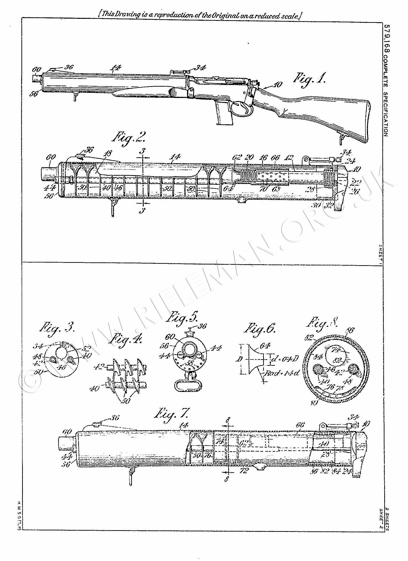
Referring first to Figures 1-6, the invention will now be described by way of example with reference to silencing the discharge of a rifle 10 having a barrel 12 of .45 in. calibre, by means of silencing-means comprising a tubular casing 14. This casing, which may be about 16 in. long, is mounted eccentrically on the rifle, so that a rear end portion constituting an expansion chamber 16 surrounds the barrel, and a front end portion constituting a baffle chamber 18 extends in front of the nozzle 20 of the barrel. This casing 14, which is circular in cross-section and may be about 2 inches diameter is mounted in spaced relation to the barrel 12 which is situated in the upper part of the expansion chamber 16.
A circular mount 22, 24 in the form of a socket for carrying the rear end of the casing 14 is fixed at the front end of the receiver 26 by means of a lock nut 28 screwed on the barrel. The circular wall 24 of this mount, on which the rear end of the casing 14 makes a sliding fit, has a short pin 30 which enters into the open-ended slot 32 in the casing at its rear end. The casing carries at its rear end a rear sight 34 and its front end a foresight 36, both of known construction.
The silencing means also comprises a plurality of baffle-plates threaded on a plurality of parallel rods that extend within the casing 14 in the direction of its length. As illustrated, two such rods 40, 42, which lie on a horizontal diameter of the casing 14, have their rear ends screwed into the end wall 22 of the mount 22, 24, and carry each a cap screw 44 at its front end. The rear end portions of these rods are of smaller diameter than the front portions on which two tubes 46, 48 are respectively carried. A plurality of substantially spiral baffle-plates 50 are threaded on these tubes 46, 48 and lie in spaced relation from the internal periphery of the casing 14. Each of these baffle-plates 50 has the form of a disc that has an eccentric perforation 52 in line with the barrel for the passage of the projectile, and has a radial slit 54 that. extends from the periphery of the disc through the perforation 52 to the centre of the disc; the two portions of the disc at opposite sides of the slit are bent so as to be spaced apart angularly one in relation to the other and lie at opposite sides of the general plane of the disc. The baffle-plates are thus substantially spiral and, as shown most clearly in Figure 4, provide a substantially spiral passage, along which the gases escaping from the muzzle of the barrel will flow. The peripheries of the baffle-plates are spaced away from the internal periphery of the casing 14 to provide at each plate a space or gap that surrounds it at the inner face of the casing for permitting solid products of combustion to pass along the inner face of the casing.
The front end baffle-plate, of which baffle-plates there may be about 13, is spaced away from an end flat plate 56, shown most clearly in Figure 5, situated at the front outer end of the casing. This plate 56 has in its lower portion an arcuate row of relatively small powder-discharge holes 58 adjacent to that part of its periphery which lies at the bottom of the casing. A short gas discharge tube 60 is carried by this plate 56 so as to lie in line with the perforation 52 and the barrel 12.
Means for preventing, or tending to prevent, the formation of a partial vacuum at the muzzle of the barrel is provided within the expansion chamber 16 in the casing 14. This vacuum-prevention means is constituted by an expansion nozzle 62 formed or provided on the muzzle 20, for which purpose the latter is screw-threaded externally, and the stem of the nozzle is screw-threaded internally. Preferably the internal face 64 of the nozzle has the shape shown in Figure 6, which shows a maximum diameter D, a minimum diameter d= 0.4D, a radius of curvature of the side face of the nozzle being 1.4d. In some cases the nozzle may be mounted on the rods 40, 42 but that arrangement is not preferred.
The silencing means described above is combined with a cylindrical shield 66, that is screwed on the barrel-muzzle 20 and lies in spaced relation with the barrel, to form a concentric annular space 68 placed in open relation with the interior of the barrel by way of a plurality of vents 70 therein. These vents 70 are disposed evenly in a plurality of rows extending around and. along the periphery of the 5 barrel, with the vents in one longitudinal row preferably staggered in relation to those in an adjacent longitudinal row, in order that the pressure of the gases shall be reduced evenly around the periphery 10 of the projectile. There may be 6 vents per row around the barrel, and these rows may be spaced about 4 in. apart. The annular space 68 is closed at its front end at the nozzle 62 which may be distinct from the shield 66 and may serve as a lock nut, for it,- but the space 68 is open at its
rear end.
In operation the column of air in the barrel and the gas leakage past the bullet first appears at the muzzle of the barrel. This is unavoidable and assists in. building up in front of the muzzle of the barrel back-pressure which assists the correct functioning of the expansion nozzle fitted to the end of the barrel.
As the bullet passes along the barrel, the said vents 70 constituting gas-discharge holes are uncovered in succession towards the muzzle, which vents serve to allow some of the gases propelling the bullet to escape into the expansion chamber, thereby still further building up the back pressure and also reducing the volume of gases flowing at high velocity behind the bullet. The short length of the barrel left intact at the muzzle end serves to steady the bullet should its balance have become upset or deranged through gases escaping behind it transversely to its path of flight. Also this short imperforate length of barrel permits the bullet to acts as a stopper in front of the gases during the period of their escaping through these vents.
When the bullet travels through the baffle-plates 50 after having passed the nozzle 62, the gases are made to swirl so that their travel is transverse to the path of flight of the bullet. It is arranged that the path of the bullet shall lie off-set from the axis of the swirl. The expansion chamber is carried right back as far as the receiver, primarily to provide increased expansion space for the gases, and secondly to produce a compact, robust and easily handled type of firearm, equipped with silencer.
When the gases strike the first baffle-plate after having left the nozzle 62, they are in a semi-dispersed state, that is, they have followed to some extent the lines of the nozzle, although there is probably still a column of concentrated gas directly behind the bullet. The effect of striking the first baffle-plate is that most of the gas is made to swirl in such a manner that the vortex of this swirl is central with the silencer tube, the longitudinal axis of the barrel and path of the bullet being offset from and eccentric to the centre of this tube. The effect of this swirl is to make the gas travel transversely of the path of the bullet, and in doing so a small proportion of it will tend te deflect and dissipate the column of high pressure gas directly behind the bullet. It is, of course, impossible for one baffle-plate to do all that is required in this direction, and therefore a number of similar plates are placed in spaced relation one behind another, each one contributing in some degree towards making the gas follow a path other than the flight of the bullet, the net result of which is that the bullet leaves the silencer with the gas following it at a greatly reduced velocity. The pressure of the gas in the silencer is higher than the pressure of the atmosphere outside, and if discharges itself from the tube 60 as a jet of gastravelling at a sufficiently low velocity as to produce very little or no sound.
In addition to this, in order that unburnt powder as well as burnt powder, refuse and solid products of combustion, shall not accumulate unduly in the silencer, particularly the live powder which on accumulation could cause serious accidents should it become ignited at any time, the baffle-plates do not fit the tube of the silencer tightly, but, as mentioned above, have a small gap around their periphery, while in the end plate of the silencer body small slots or holes 58 are pierced so that the above debris can be discharged or fall out as the case may be. The presence of these additional holes in the end plate provides additional exits for the gas, but this is purely incidental and does not affect the resulting sound in any way.
The expansion nozzle 62 is provided for the purpose of preventing a vacuum from being formed at the muzzle. The collapse of this vacuum produces a sharp "crack" which heretofore has not been suppressed except by means of sound-absorbing or damping material, such as felt. This “crack" is normally transmitted through the wall of the silencer of the type described, but by the provision of this nozzle, this vacuum is prevented from being formed, and therefore there is no "crack" to be silenced.
The vents 70 in the barrel surrounded by the shield 66 reduce the volume of gas following the bullet and prevent the gases which are travelling at high velocity from impinging directly on the wall of the silencer, which would cause a noise. The invention thus provides an improved robust, compact and silent firearm, whereof the barrel and silencer form an unitary structure which can be attached to a firearm having any mechanism whether of the single shot, repeater or automatic type of feed.
Another advantage of reducing the gas pressure behind the bullet just prior to its leaving the muzzle of the barrel is that when the bullet becomes unsupported after leaving the muzzle, there is not the same pressure of gas behind it as there would normally be to upset its balance.
In actual practice a rifle bullet travels many feet from the muzzle of a gun before it rotates freely about its own centre of gyration in true flight. This upsetting is caused by the gases fallowing it at high pressure from the muzzle, It is, therefore, reasonable to presume that if this velocity and gas pressure can be reduced just before the bullet leaves the barrel, the effect of this disturbance will be beneficially reduced, thereby improving accuracy in use of the firearm.
The construction of silencing means shown in Figures 7 and 8 is similar to that described above with reference to Figures 1-6, but differs therefrom in that the baffle-plates in the casing 14 are arranged in two groups, whereof a front group comprises baffle-plate 50 constructed as described above, and the rear group is arranged between the barrel muzzle and the front group, and comprises baffle-plates each of flat construction. As illustrated, the rear group comprises three baffie-plates 72, 74 and 76, whereof the plate 76 situated next adjacent to the group of plates 50, is of larger diameter than the plates 72 and 74, and makes a snug fit in the casing 14. The two plates 72 and 74 have each a shallow arcuate peripheral recess 78 which, when in its position of use, lies in the lower part of the silencer. The end baffle-plate 76 of the rear group situated remote from the nozzle 62 has in place of the arcuate peripheral recess an arcuate row of relatively small holes 80 lying opposite to the arcuate recess in the next adjacent baffle-plate 74. Each of these baffle-plates of the rear group has in it a perforation or aperture 82 in line with the perforations 52 in the front group of baffle-plates for providing a throughway for the projectile in line with the central longitudinal axis of the barrel. In. this modified construction the gases issuing from the nozzle behind the projectile are throttled somewhat by the rear group of baffle-plates before they have imparted to them the swirling motion by the front group, whereby the efficiency of the silencer is enhanced.
![]()
![]() In some cases it is found that the gas impacting on the metal shield 66 shown in Figure 2, which is slightly longer than the apertured portion of the barrel, is liable to produce an undue amount of noise. In order to obviate this defect, as shown in Figures 7 and 8, a sound-absorbing device in the form of a liner is provided for that part of the casing 14 of the silencer which surrounds the vents 70, which liner extends when in use, from a situation in front of the expansion nozzle 62, to the rear of the silencer casing 14. As illustrated, this liner comprises a tubular layer 82 of sound-absorbing yield-able material protected on the inside by a thin metallic sheath 84. The liner also preferably comprises a thin metallic sheath 86, on the outside of the sound-absorbing material which may be of animal, vegetable or mineral origin and may be comprised of felt, rubber or rubberised fabric, asbestos, lead-wool or the like. The objects of providing the sound-absorbing device with the internal or both internal and external metallic sheath are (1) to avoid disintegration of the sound-deadening yieldable material by the impact on it of the hot gases escaping from the vents in the barrel, (2) to avoid contamination and fouling of the sound-deadening material by the products of combustion, and (3) to enable the liner to be readily removed and cleaned.
In some cases it is found that the gas impacting on the metal shield 66 shown in Figure 2, which is slightly longer than the apertured portion of the barrel, is liable to produce an undue amount of noise. In order to obviate this defect, as shown in Figures 7 and 8, a sound-absorbing device in the form of a liner is provided for that part of the casing 14 of the silencer which surrounds the vents 70, which liner extends when in use, from a situation in front of the expansion nozzle 62, to the rear of the silencer casing 14. As illustrated, this liner comprises a tubular layer 82 of sound-absorbing yield-able material protected on the inside by a thin metallic sheath 84. The liner also preferably comprises a thin metallic sheath 86, on the outside of the sound-absorbing material which may be of animal, vegetable or mineral origin and may be comprised of felt, rubber or rubberised fabric, asbestos, lead-wool or the like. The objects of providing the sound-absorbing device with the internal or both internal and external metallic sheath are (1) to avoid disintegration of the sound-deadening yieldable material by the impact on it of the hot gases escaping from the vents in the barrel, (2) to avoid contamination and fouling of the sound-deadening material by the products of combustion, and (3) to enable the liner to be readily removed and cleaned.
This liner may be used without the shorter sleeve 66, preferably of mild steel, that surrounds the vents and serves to disperse the hot gases issuing from them.
When inner and outer metallic sheaths are provided they may be sealed at their ends so as to enclose the sound-absorbing material fluid-tight. The liner can then be washed or otherwise cleaned, if necessary, without affecting the sound-absorbing material. Owing to the outer metallic sheath of the liner it can be readily slid into and out of position in the silencer casing.
Each sheath 84 and. 86 may be composed of any convenient metal, such as brass foil.
The baffle-plates 72 and 74 are of smaller diameter than the baffle-plates 76 in order that they may lie within the sound-absorbing device.
A sound-absorbing device similar to that described with reference to Figures 7 and 8 may be provided in the construction of silencer shown in Figure 2, in which case it may surround some of the baffle-plates 50.
Another function of either construction of silencer described is that of eliminating flash, which is particularly advantageous in the case of firearms, such as a machine-gun, used at night.
Each construction of silencer described above is self-cleaning, and will also discharge foreign matter, such as sand, which has inadvertently been permitted to enter it.
Various modifications may be made in the details of construction described above without departing from the invention. For example, instead of using an expansion nozzle 62, a nozzle of internal frusto-conical shape may be employed. Also, in some cases more than two rods may be provided for carrying the baffle-plates. Moreover, instead of spacing all of the baffle-plates 50 away from the internal periphery of the casing 14, only some of them may have gaps at their peripheries. Further, if desired, the baffle-plates may be integral one with another and constitute a spiral structure. Again, in some cases the rods 40 and 42 may be dispensed with.
Having now particularly described and ascertained the nature of my said invention and in what manner the same is to be performed, I declare that what I claim is :‑
1. Silencing means of the type described, wherein the baffle-plates are each in the form of a disc of spiral or substantially spiral formation and are arranged to cause the gases emitted from the barrel to swirl about an axis that is offset from the path of the projectile through the baffle-plates, each of which baffle-plates has an eccentric perforation for the passage of the projectile, characterised in that baffle-plates situated towards the front end of the silencer have each a radial slit that extends from the periphery of the disc, preferably through the perforation, the two portions of which disc at opposite sides of the slit are bent so as to be spaced apart angularly one in relation to the other and lie at opposite sides of the general plane of the disc.
2. Silencing means according to claim 1, comprising means for preventing, or tending to prevent, the formation of a partial vacuum at the muzzle of the barrel.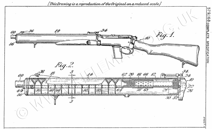
- Silencing means according to claim 2, wherein an expansion nozzle is situated, or arranged to be situated, at the muzzle of the barrel, characterised in that the nozzle is so constructed and arranged as to constitute the vacuum-prevention means.
- Silencing means according to claim 1 or claim 2, wherein the casing extends, or is constructed to extend, rearwardly around the barrel beyond the muzzle 65 thereof for providing a rearwardly-closed expansion chamber situated between the muzzle and the receiver of the firearm.
- Silencing means according to any of the .preceding claims, wherein the peripheries of some or all of the baffle-plates are spaced away from the internal periphery of the casing to provide an annular space or gap that surrounds the baffle-plates at the inner face of the casing.
- Silencing means of the type described comprising baffle-plates arranged in two groups, whereof a front group comprises baffle-plates constructed as set forth in claim 1, and the second group is arranged between the barrel-muzzle and the front 80 group, and comprises a plurality of baffle-plates which are each of flat construction, one or more of which have each a shallow arcuate peripheral recess which, when in its position of use, lies in the lower part of the silencer.
- Silencing means according to claim 6. wherein the end baffle-plate of the second group situated remote from the barrel-muzzle has in place of the arcuate peripheral recess an arcuate recess of relatively small holes lying opposite to the arcuate recess in the next adjacent baffle-plate of the second group.
- Silencing means according to any of the preceding claims, wherein an end flat baffle-plate situated at the front outer end of the casing is formed with an arcuate row of relatively small holes adjacent to that part of its periphery which lies at the bottom of the casing.
- Silencing means according to any of the preceding claims, wherein the baffle-plates are supported by a plurality of parallel rods that are supported at the front and rear ends and extend in the direction of length of the casing.
- Silencing means according to any of the preceding claims, in combination with a cylindrical shield that lies or is arranged to lie surrounding the barrel at the rear of its muzzle and in spaced relation therewith to form an annular space placed in open relation with the interior of the barrel by way of a plurality of vents therein.
- Silencing means according to Claim 10, wherein the vents are disposed evenly in a plurality of annular rows around the periphery of the barrel, with the vents in one row preferably staggered in relation to those in an adjacent row, in order that the pressure of the gases shall be reduced evenly around the periphery of the projectile.
- Silencing means according to Claim 10 or Claim 11, wherein the annular space is closed at its front end outside the barrel and is open at its rear end.
- Silencing means according to any of the preceding claims for use with a barrel provided with a plurality of vents in its front end portion, comprising a sound-absorbing device in the form of a liner for that part of the casing of the silencer surrounding the vents, which liner will extend, when in use, from a situation in front of the barrel-muzzle to the rear of the silencer casing, and comprises a tubular layer of sound-absorbing yieldable material protected on the inside by a thin metallic sheath.
14. Silencing means according to Claim 13, wherein the liner also comprises a thin 15 metallic sheath on the outside of the
sound-absorbing material.
- Silencing means according to Claim 13 or Claim 14 wherein some of the baffle-plates of the second group thereof set forth in Claim 6, are surrounded by the front end portion of the liner.
- Silencing means according to Claim 1 as shown in Figures 2, 3, 4, 5 and 6, or modified according to Figures 7 and 8 of the accompanying drawings.
Dated this 7th day of June, 1944.
BOULT, WADE & TENNANT,
111 & 112, Hatton Garden,
London, E.C.1,
Chartered Patent Agents.
Leamington Spa : Printed for His Majesty's Stationery Office, by the Courier Press.-1946. Published at
The Patent Office, 25, Southampton Buildings, London, W.0.2, from which copies,
price 1s. 0d. each (inland) ls. ld. (abroad) may be obtained.
Whilst investigating the building of the De Lisle carbines, we considered the fact that they were constructed in comparative haste using whatever components were either readily available or had become obsolete from then current needs.
This was why old out-of-service rifles were cannibalised for parts, including the SMLE receiver and the butt furniture.
Yes, Thompson sub-machine-gun barrels would have been currently required spares for their parent weapons, but could presumably be spared in the small numbers required.
Steel and aluminium tube, rod and sheet formed the greater part of the remaining components, but one notable item that required special manufacture was the walnut fore-end/hand-grip.
Obviously these could be made from new timber, but, in the light of the waste-not-want-not thinking of the time, it was likely that a used source of walnut was sought.
This is pure supposition on our part, but we looked at the small fore-end on the carbine and considered the possibility that it could have been cut out of a used piece of timber; the obvious candidate for which was another surplus SMLE butt, of which there were many more than surplus rifles.
To that end, we took an old SMLE butt and set to work.
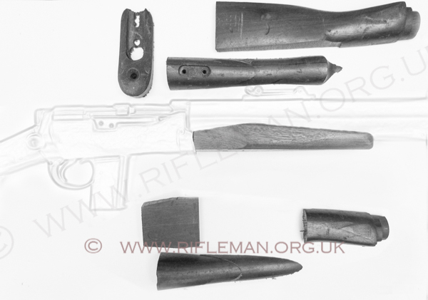
As can be seen by the roughed-out fore-end and the off-cuts in the image above, the theory was proven perfectly practicable.
Further comprehensive information on the De Lisle carbine,
well researched by the Deputy Curator of the National Firearms Centre collection, can be found at
See also the Enfield Rifle No.4T sniper training rifle
Peter Laidler & David Howroyd - "The Guns of Dagenham" - ISBN 9 780889352 04 9 - 1996
I.D. Skennerton - "De Lisle's Commando Carbine" - Small Arms Series" - ISBN 0 949749 00 1 - 1981
* I.D. Skennerton - "Special Service Lee-Enfields ... Commando and Auto Models" - Small Arms Identification Series No.13 - ISBN 0 949749 37 0 - 2001
J. David Truby - Machine Gun News - "De Lisle? Never Heard of it!" May 1992
John Minnery - "The Commando Carbine" -
Robert T. Rome - "WWII Silent Killer Still Lives" - Gung-Ho - June 1984
or view the comprehensive "Gung-Ho" magazine article of 1984

See this website's Raison d'être