THIS IS THE U.K. HISTORIC ARMS RESOURCE CENTRE.. - ..BEST VIEWED ON PC.. - ....FREE OF COOKIES, TRACKING & ADVERTISEMENTS
The Martini-Henry Rifle and Action
Please be aware that some specialist rotational imagery on these pages may take longer than usual to load
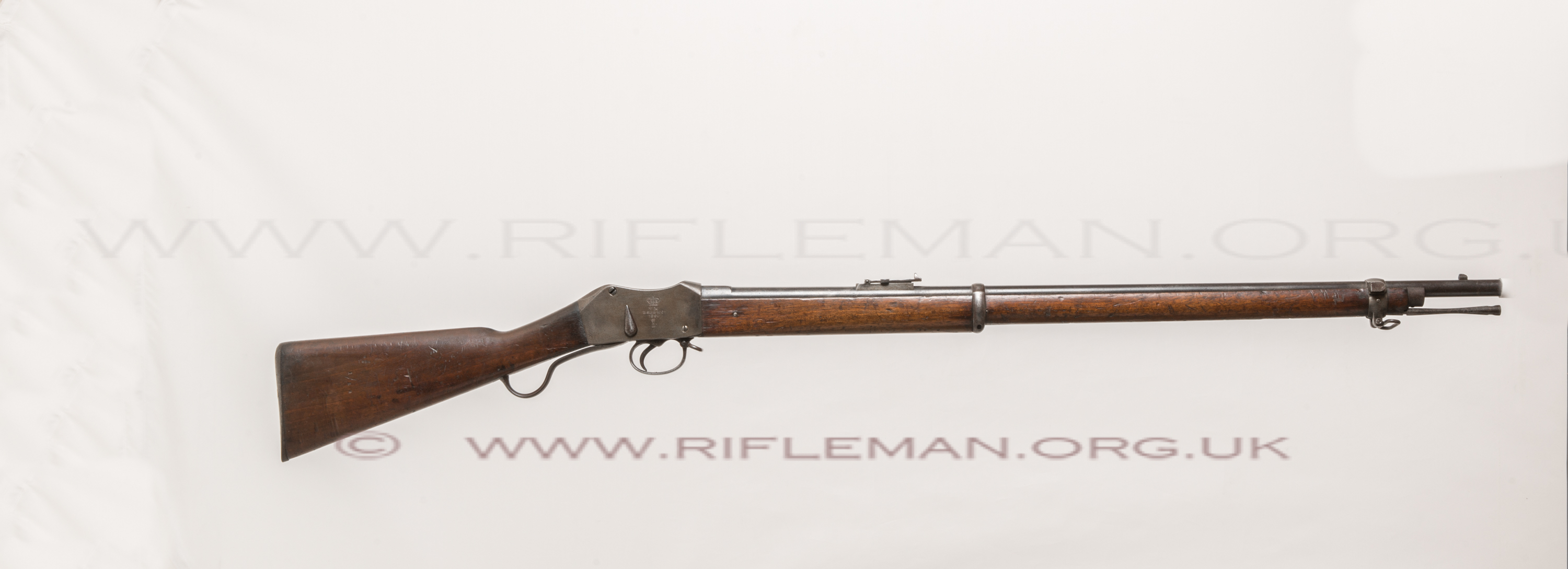
Famously employed during the Zulu Wars, the Martini-Henry rifle is one of the best known British service rifles.
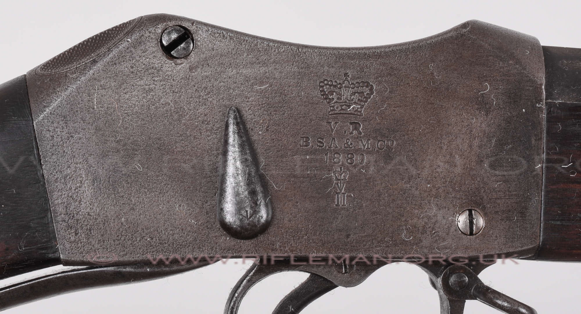
This rifle was manufactured by the Birmingham Small Arms & Metal Co., and is dated 1880. It is stamped as a Mark II beneath the Broad Arrow military acceptance mark.
Drag horizontally to rotate subject - Click to zoom and drag to pan - Full screen viewing from expansion arrows.
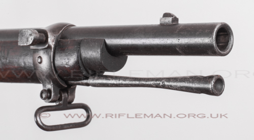
Below: the muzzle, front barrel band with bayonet lug and sling swivel, the plain fore-sight, steel fore-end nose-cap and ram-rod.
The right-hand-side of the action body, showing the falling-block fulchrum-pin top left, and the 'tear-drop' cocking indicator that allows the firer to check, by feel alone, whether or not the action is cocked.
This rifle is of Victorian manufacture, evidenced by the mark "VR" benath the crown stamp.
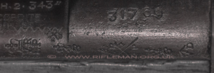
Below: the rifle's serial number on the barrel, and the proof marks on the action body.

Left: marks confirmimg the .577/.450 inch calibre, the cordite propellant load of 38½ grains, and the bullet weight of 480 grains.
Right: the serial number 31769, and proof and inspection marks stamped below, with the crossed swords military acceptance mark bottom right.
 ...........
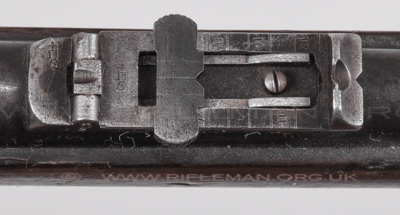
Below left: the standard issue tangent leaf rear-sight with elevation slide, calibrated for 100, 200, 300 and 400 yards.
Right: the elevation marks for greater ranges when the leaf is lifted in the vertical position.
 ...........
Below: the leaf in the raised position shown from in front, the "Broad Arrow" military acceptance stamp above the bottom hinge.

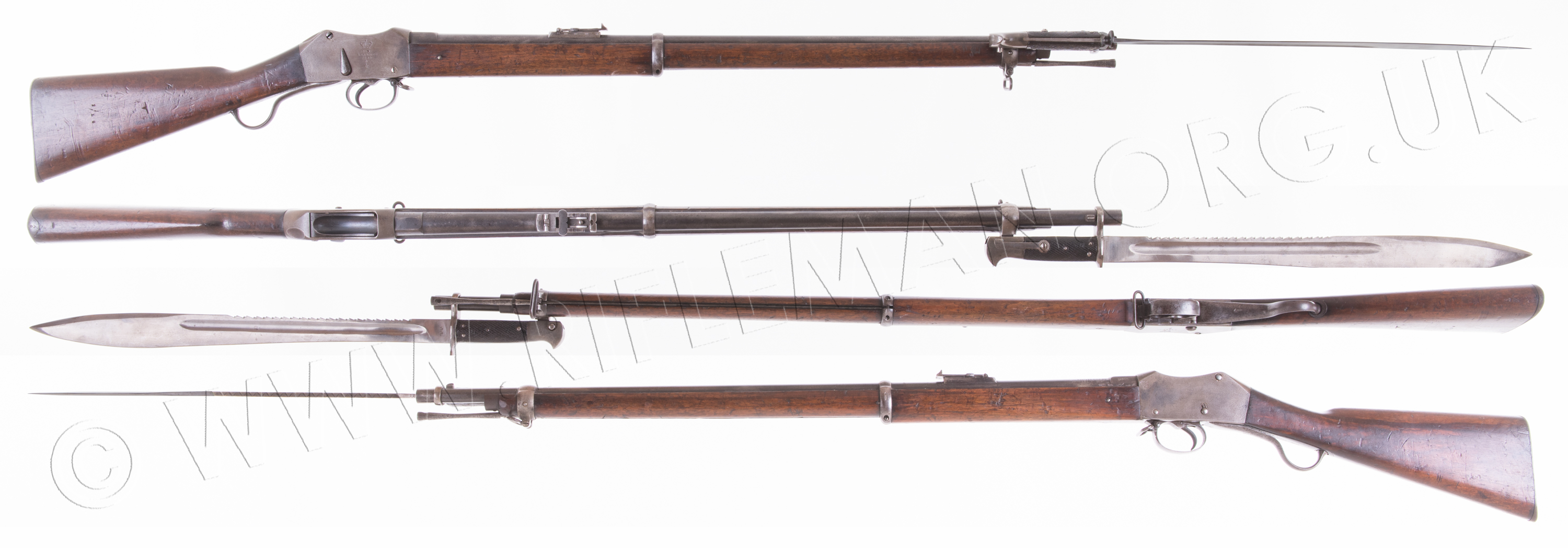
Below: the rifle with socket bayonet fitted.
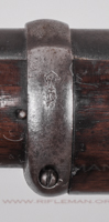
The mid barrel-band with inspection mark.
The rifle with socket bayonet fitted, with its locking ring against the barrel's bayonet lug.

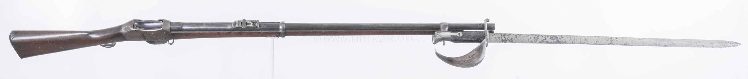
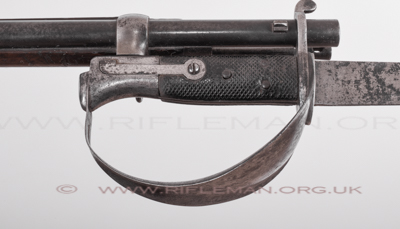
Below: the rifle fitted with the alternative Naval cutlass bayonet.
Close-up of the right-hand-side attachment.
And the bayonet, fitted to the rifle, shown from beneath.

The cutlass bayonet blade's ricasso Enfield inspector's view mark - Crown over "E" over "59",
Broad Arrow acceptance stamp over "WD" mark .
This War Department mark was only used from 1856 to 1895.
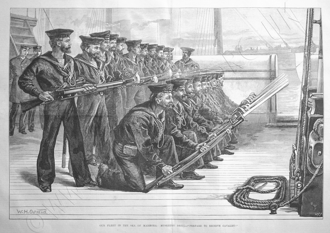
The Illustrated London News of April 1874 printed a fine contemporary engraving of
on-board musketry training with the rifle and cutlass bayonet.
The data table will be completed soon
DATA TABLE - ALL MEASUREMENTS AS VIEWED |
FIREARM |
IMPERIAL |
METRIC |
| Designation or Type : |
Military Service Rifle |
- |
| Action Type : |
Falling block |
- |
| Nomenclature : |
Martini-Henry |
with serial no. |
| Calibre : |
.577/.450 |
- |
| Weight : |
8 lbs. 7 ozs. |
2.40 kgs |
| Length - Overall : |
49 inches |
cms |
| Length - Barrel : |
33.2 inches |
cms |
| Pull : |
14.5 inches |
cms |
| Furniture : |
Walnut |
- |
Rifling - No./Type of Grooves : |
7 - ratcheted |
- |
| Rifling - Twist : |
1 turn in ? inches - RH |
1 : 40 cms |
| Rifling - Groove width : |
inches |
mm |
| Rifling - Land width : |
inches |
mm |
Rifling - Groove depth at muzzle : |
inches |
mm |
| Sight - Fore : |
|
- |
| Sight - Rear : |
|
- |
| Sight - Radius : |
inches |
cms |
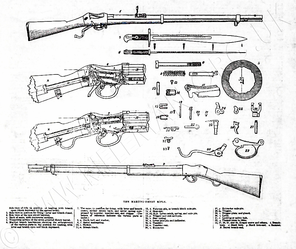
Another bayonet used with the rifle was the rare "Elcho" saw-back model, of which little more than a thousand were believed produced from the design by Lord Elcho, and a drawing of which is shown below, including cross-sections of the rifle's action with the falling block open and closed.
Below: the rifle fitted with the Elcho bayonet.
Hover over or Click image to bring up hi-res file and magnifier
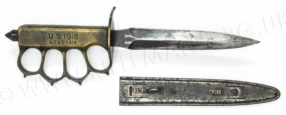
Only loosely associated with this page's subject rifle, but a highly unusual item was spotted by us a few years ago at a London Arms Fair. This Elcho bayonet had been fitted to the knuckle-duster handle of a First World War 1918 dated U.S. standard issue Mk.1 trench knife, increasing its length, weight and lethality near fourfold. The latter knife is itself a rare beast nowadays, but the combination, presumably a WW1 adaptation, must be approaching unique.
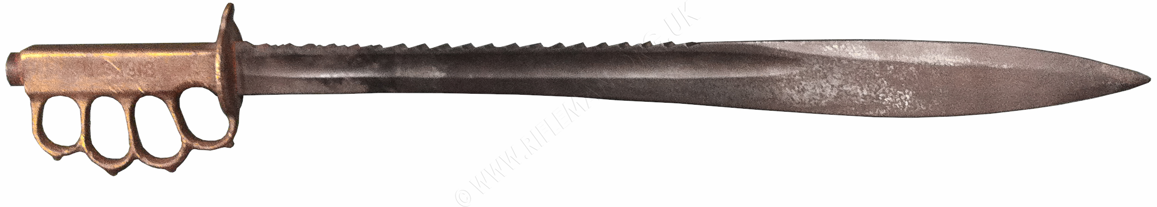
The original Mk.1 Trench knife manufactured by L.F.& C. -1918
to approximately the same scale.
A multi-photo stacked image of the bore clearly shows the "ratchet" cross-section
of the seven rifling grooves of the Henry barrel
.
(44 exposures of 3 seconds at f11)
Click image to bring up hi-res file and magnifier
DIFFERENT GROOVE/LAND DESIGNS WERE USED IN THE MARTINI-METFORD & MARTINI-ENFIELD RIFLES
MANY OF WHICH WERE SUBSEQUENTLY CONVERTED TO "MINIATURE"
CALIBRES
BY GUNSMITHS SUCH AS C.G. BONEHILL & W.W. GREENER
Please also visit the pages for the W.W.Greener
Martini Target Rifles or the Parker-Hale
CMT (Converted Martini Target) rifles page
and the in-build C.G.
Bonehill Converted Martini rifles page
A warning is necessary to anyone proposing to adjust their own martini trigger, either a full-frame full-bore rifle, or a small bore conversion, or a small-frame, small-bore target or sporting rifle.
. For further details plase see THE MARTINI
and LEE-ENFIELD ACTION TRIGGER PULLS
Shown below is a partly disassembled large-frame Martini-Henry action
used by C.G. Bonehill for their conversion of the .577/450 centrefire
service rifle to .22 rimfire, and marketed by the Society
of Miniature Rifle Clubs. There follow on this page an exploded diagram
of the action, brief details of its origin, the patent application and
drawings, and an extract from the 1897 "Instructions for Armourers" detailing action disassembly, reassembly and adjustment.

The
"falling-block" breech-block and its axis split-pin are to be
seen at the top of the image.
This block contains the striker and spring in within a separate component.
The first design of this type of falling-block action
is credited to the American Henry Peabody,
but, for British service, the
improvements initially patented by Freidrich von Martini in 1868 were
taken up in a rifle utilising a design close to that of his 1871 Patent
shown below.
That was the year in December of which the Martini-Henry
rifle, in .577/.450 calibre, was
brought into service, fitted with a barrel
rifled with the 'ratchet' cross-section grooves
introduced by Alexander
Henry.
Patent No. 2925. Prioleau, C.K., [Martini, F. von].
Oct 31st. 1871
Breech actions, hinged breech-block. – Relates to
the class of small-arms described in Specifications No. 2305, A.D. 1868
and No. 1144, A.D. 1871. The breech-block c,
Fig. 6, carries the firing-pin d, which is engaged by the tumbler g fulcrumed at h. The short arm g' of the tumbler
rests upon a tumbler rest i, pivoted at k. The short
arm m' of the trigger m is notched to receive the nose i' of the tumbler rest when the arm is cocked. When the
rest i is released by pulling the trigger the pressure of the
tumbler g causes it to turn upon its axis so as to allow the
tumbler to pass. In re-cocking the arm, the hand-lever n comes
in contact with a sliding pin o and causes it to rotate the rest i upon its axis under the arm of the tumbler until the
trigger spring forces the arm m' into engagement therewith. The
firing-mechanism is locked in
position by means of a bolt arranged to slide along the trigger plate q and actuated by a suitable face on the lever n, a
projection on the bolt takes under a projection or lug on the trigger
thereby locking the trigger. The trigger is unlocked by withdrawing the
bolt by means of a thumb-piece attached thereto. By pushing forward the
bolt the locking mechanism may be put out of action. In another arrangement
of the breech action, the tumbler rest is recessed to receive the end
of a spring which, when the tumbler is in the cocked position, tends to
force the rest into a notch formed in the short arm of the tumbler. Fig.
11 shows a cartridge extractor arranged in connection with a breech action.
The extractor lever r, fulcrumed at t, is split at r' so as to form a powerful spring. The extractor is actuated by a bar r3,
which slides in the trigger plate q and is operated by a face n2 on the hand-lever n when the lever is depressed.
In extracting the cartridge case, the slit r' is closed by the pressure exerted until the case is loosened, and then
the upper ends of the extractor spring forwards and expel the case. In
one modification, the extractor lever is made solid and the bar r3 is curved and formed with a slit so as to cause the bar to act as a spring.
In another arrangement, the extractor levers, provided with slits, are
made separate and are mounted upon the same pin. The long arm of a lever,
pivoted upon the above pin, is operated by the breech-block so as to cause
the short arm of the lever to come into contact with the extractor levers
and cause them to extract the cartridge case. The Provisional Specification
states that the arrangements for locking the firing-mechanism and for
extracting the cartridge cases may be applied to other breech actions
than those referred to.
___________________________________
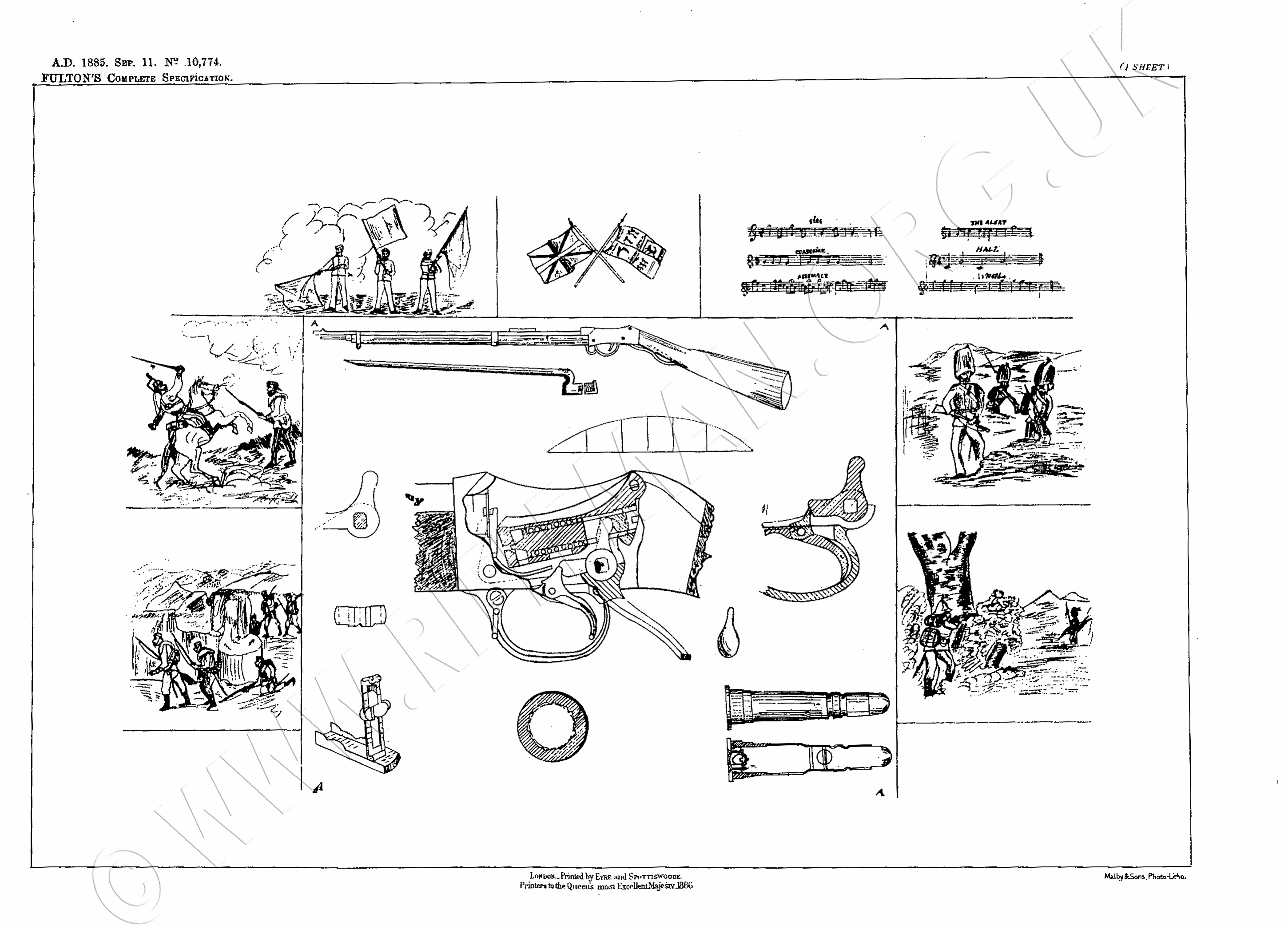
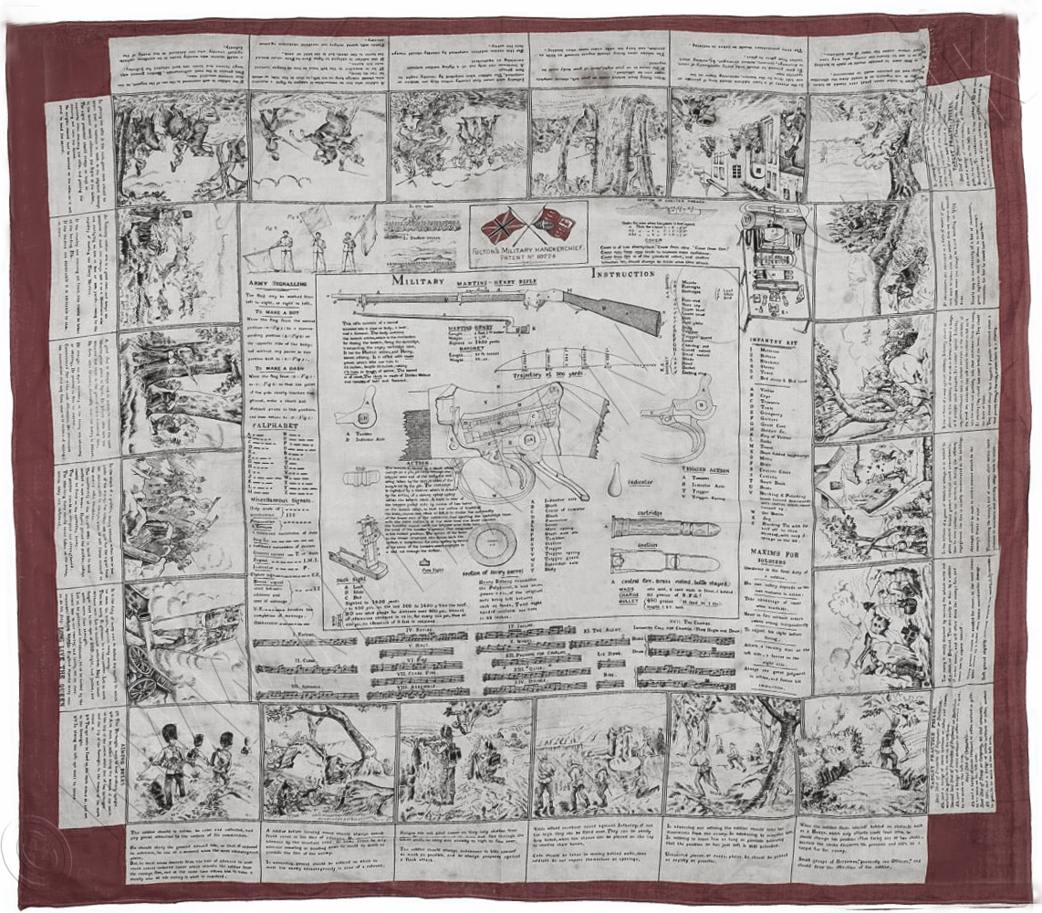
The long famous gunsmiths Fulton's of Bisley patented the designs for two handkerchiefs. One was for the Martini-Henry, and the other was for the later "Long" Lee-Enfield rifle. The original patent for the central portion of the former is shown below. The outer sections of each design consisted of information on signalling, equipment, maxims for soldiers, music scores for relevant songs, and a series of drawings with text illustrating combat situations.
The other handkerchief is shown on the page for the "Long-Lee" rifles.
Hover over or Click image to bring up hi-res file and magnifier
The Martini-Henry version of the handkerchief is shown below.
___________________________________
For training purposes a number of skeletonised actions were used,
examples of which lie in the Royal Armouries as part of the original Pattern Room collection.
The earlier, .402-inch calibre 'First Pattern' is mounted on a wooden base; exhibit no. PR.5559
This was the mid 1880s "Long Lever" action of the then updated rifle for improved extraction and with a strengthened receiver.
Approximately 65,000 were manufactured with the new rifling in this smaller calibre, but this Mk.1 Enfield Martini was rendered obsolete in 1887 with the introduction of the .303-inch calibre Martini-Metford (followed by the Martini with the newer Enfield rifling).
Many of the .402-inch barrelled rifles had their barrels bored out and returned to the .450" calibre, then being afforded the nomenclature Martini-Henry Mk.VI.
The second, accepted for service in the List of Changes no.3416 of 1887, is exhibit no. PR.5560.
It is recorded as being of .450-inch calibre and listed as the carbine action.
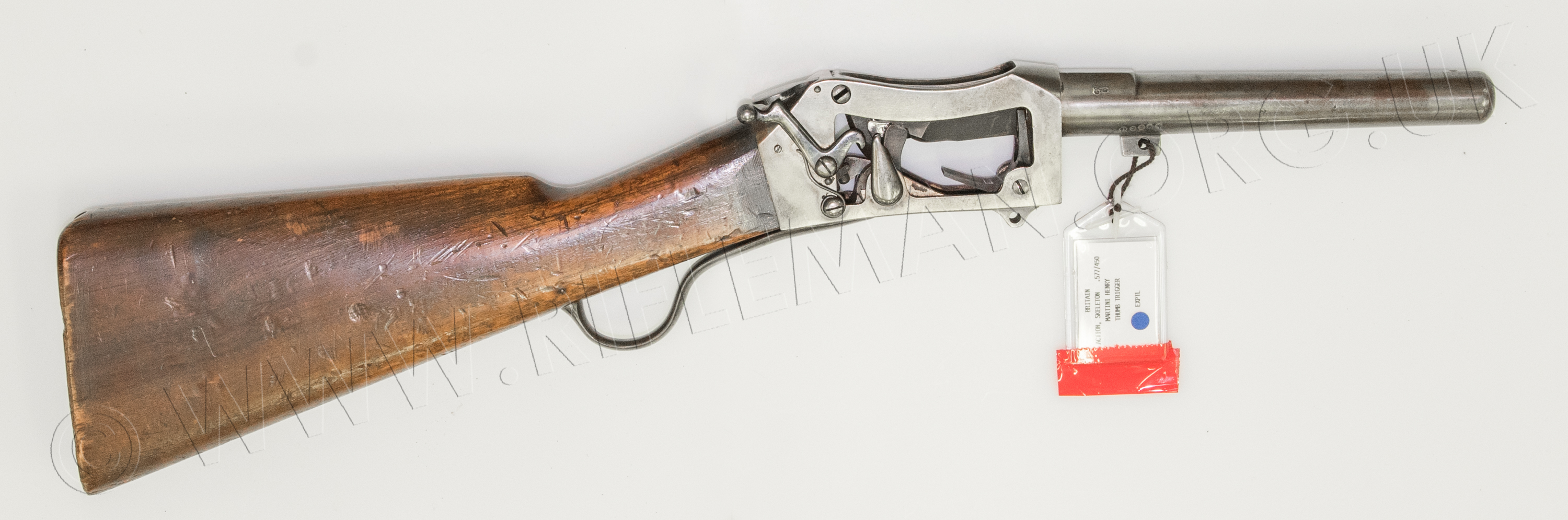
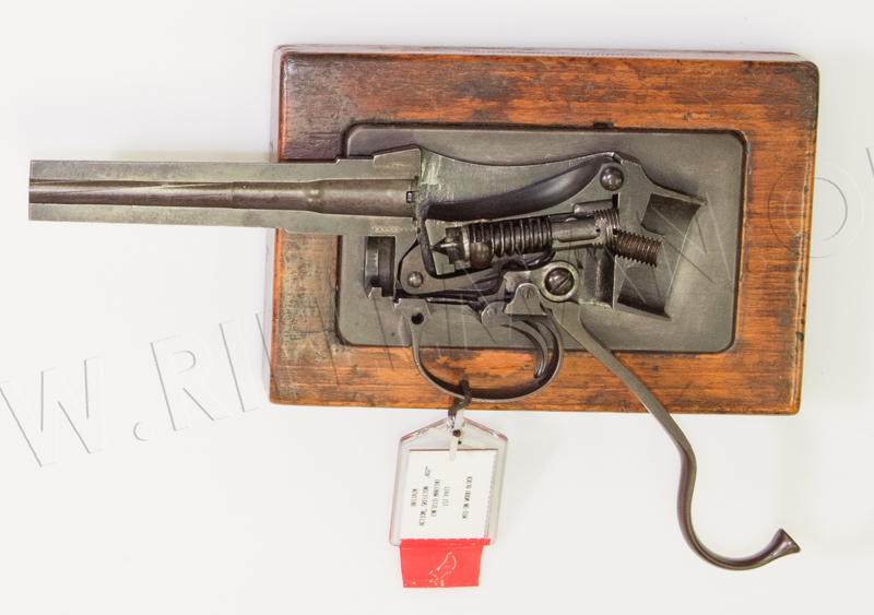
A further example in the collection is rather more than a standard skeleton,
but is a particularly rare cut-away of the rifle fitted with an experimental thumb-trigger.
The unit bears serious inspection of the method in which it operates.
It is again of the standard issue .577/.450-inch calibre.
The collection's exhibit record no. is PR.5666
The date of the skeletonised action is ca. 1870
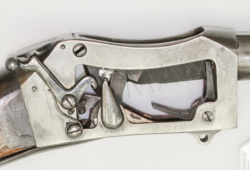
To assist with understanding the trigger's action, click the image below for a short video clip.
The safety lever with its catch over the cocking-indicator is pressed to release the latter,
allowing the flat trigger on top of the rear of the action body to be depressed to fire the rifle.
Taken from the "INSTRUCTIONS FOR ARMOURERS
- 1897"
linked to complete document with drawings
INSTRUCTIONS FOR THE CARE, REPAIR, &c., OF
MARTINI-ENFIELD AND MARTINI-METFORD ARMS.
1. All parts connected with the breech action will be kept
perfectly clean.
2. Rangoon oil only will be used for this purpose; the use of cutting
substances, such as emery, sand-paper, &c., or of the buff stick being
strictly forbidden.
3. Care must be taken not to injure the face, of the block in cleaning,
especially the striker hole, or to enlarge the chamber by cleaning, the
stick cleaning chamber with wire gauze or an oiled rag. only should be
used for this purpose (a bright chamber not to be insisted upon).
4. See instructions for cleaning magazine arms.
5. Rangoon oil should be applied to the following parts of the action
occasionally :
Knuckle and knuckle seat of block.
Axis pin of block.
Lever ends and seat in block.
Lever and tumbler axis.
Trigger axis.
Trigger nose and spring.
Extractor axis.
Main spring, striker.
Stop nut and tumbler.
DIRECTIONS FOR STRIPPING THE ACTION.
RIFLE AND CARBINES.
1. Close the action.
2. Knock out the block axis pin by placing a drift on the slit-head of
the pin, first removing any dirt there may be in the slit.
3. Depress lever, and hold down front end of block with left thumb, close
the lever, and the block will spring uut.
4. Take out block, turn the curve in keeper screw fair with the curve
in the stop nut, unscrew the stop nut; the striker and main spring will
then fall out.
5. Turn the keeper screw head of lever axis fair with axis hole, press
out axis pin, and take out the tumbler.
6. Turn out extractor axis screw, and remove extractor, trigger guard
and lever.
7. Turn out the screw holding the trigger spring, and take out the spring.
8. Turn out axis screw of trigger, take out trigger.
DIRECTIONS FOR STRIPPING FURNITURE, BARREL, AND STOCK.
RIFLE, M,-E., MARK I.
1. Draw clearing rod, first unscrewing the rod to the left.
The rod will then draw straight out.
2. Remove upper band pin
3. Partly unturn band screws and take off bands. 'The lower band stop
pin should not be removed.
*4. Pull off stock, &c.
5. Take off butt plate.
6. Turn out stock bolt, and take off butt of stock.
CARBINES (ARTILLERY, M.-M., MARK II and MARK III, M.-E.,
MARK I).
1. Draw clearing rod, first unscrewing the rod to to the
left.
2, Remove nosecap screw, drive nosecap off fore-end, and turn so that
the fore-sight can pass through the slot in nosecap.
3. Remove barrel stud pin in A.C.M.-M., Mark II, and drive the stock fore-end
off the barrel stud at the breech end with the wood drift.
4. Pull off stock from muzzle of barrel, and the hook will disengage from
the end of the body in A.C.M.-M., Mark III, and M.-E., Mark I.
5. As directed for the rifle.
6. .............. " ...................
* For M.-E, Mark I rifle, see (4) for carbines.
DIRECTIONS FOR ASSEMBLING ACTION, BARREL,
STOCK, AND FURNITURE.
RIFLE, M.-E., MARK I.
1. Replace butt of stock, observing that the stock bolt washer is in its
place in the stock butt, screw up stock bolt.
2. Screw on butt plate.
† 3. Place the hook fore-end &c.
4. REplace bands and turn home band screws.
5. Replace upper band pin.
6. Replace clearing rod in groove.
7. Place trigger in guard, and screw up axis screw.
8. Replace trigger spring, taking care that the nose of the trigger spring
is under the trigger; screw in the- trigger spring screw.
9. Place lever and tumbler in trigger guard, slide guard with lever and
tumbler into the body, and replace axis pin with indicator pointing upwards
in the direction of the block axis pin, and screw round keeper screw head
to its proper bedding.
10. Replace extractor and turn in axis screw.
11. Place striker in block and drop in main spring, screw home stop nut,
and turn keeper screw head into its bedding.
12. Turn striker round until the wider side of slot is downwards.
13. Place the block in body with the front end lowest; hold the lever
with right hand, the thumb pressing the indicator forward, the trigger
being pressed back by the forefinger; press hard on the knuckle of block
with the heel of the left hand to force it into its seat; at the same
time depress and work the lever to get the tumbler into the slot in the
striker.
14. Compress the sides of the block axis pin, preparatory to placing it
in the body. Place it in the body.
† For M.-E., Mark I rifle, see (3) for carbines.
CARBINES (ARTILLERY).
1 & 2 As directed for the rifle.
3. Place the hook fore-end in the body so as to engage inside recess,
pressing the stock up to the barrel at muzzle.
4. Replace nosecap, and turn home nosecap screw.
5.6.7.8.9.10.11.12.13.14.-As directed for the rifle
REPLACING COMPONENTS.
RIFLES AND CARBINES.
Adjustment in Loading Position.
1. If the block be too high, the bearing surface at A (fig. 1) of the
lever may be depressed by means of a punch to the breadth of the corresponding
surface on the tumbler. If an adjustment of more than '01 of an inch is
required, a new lever should be fitted.

2. Should the block be too low, an amount not to exceed .01-in. may be
added to the bearing surface at A by carefully drawing out the metal at
that point ; but should more than .01-in. be required (which will rarely,
if ever, be the case), a new lever should be fitted.
Adjustment in Firing Position
1. When the block is in the firing position, should the
striker strike the cap too high, an amount not exceeding .01-in. taken
off the bearing surface of the lever horns at B will be sufficient to
rectify the error.
2. Should the striker strike the cap too low the horns of the lever may
be drawn out between the lines indicated at D not to exceed .01-in., care
being taken not to spread the horns or set them out of position at C.
Extractor.— When the block is at the loading position the
point A (fig. 2) should be just free from the under side of the block.
When the block is depressed to the lowest position it should bear on point
B, holding the extractor firm ; and should the lever at E touch the guard
so as to prevent the block doing this, the guard may be filed to allow
the lever to be clear.
The point D should be on the guard when the extractor is at its lowest
position ; if it will not bed down, the fault must be looked for on the
head of the trigger spring screw ; if this stands too high, it should
be filed flat.
Trigger.-- In replacing a trigger, the nose must not be touched
in making the pull-off, but the adjustment made by Altering the angle
of tumbler bent by scraping the face.
Trigger spring.— ln replacing a trigger spring, care must
be taken that the head of the screw beds well down on the spring, and
that the point does not bear on the guard swivel screw.
Guard.— In replacing guard, it should be placed in the
body and the indicator fixed in position—notice that the guard drops
freely into the body without side pressure ; if the extractor axis hole
is not fair in both guard and body file the nib resting on front of body,
if required, tun tap to regulate the hole, and put in axis screw: See
that the indicator is perfectly free to revolve.
Tumbler.-- In replacing a tumbler, it should- pass firmty on
to, but not be driven, hard upon the squares of the indicator ; it should
also work freely between the horns of the lever
Indicator.—Remarks same as upon tumbler.

Lever.-- In replacing a lever, the bearings at point A (fig.
3) should be free when the lever is depressed, otherwise it prevents the
block from having its full fall.
The end of the lever must be set to drop freely into the lever catch block;
care must also be taken that the lever beds on its seat
at the under side of socket end of body.
The levers issued with the spare parts are for long butts — they
will require setting for short butts — a slight blow with a mallet
is all that is required to make them drop freely into the lever catch
block; the levers for long butts are issued in preference to levers for
short butts, as the adjustment required by the former to fit them to short
butts is more simple than to adjust a lever for a short butt to a long
butt.
Striker.—When replacing, care must be taken the the larger
part of the slot is downwards, and that the striker is correct to gauge
for length and radius of point.
Examination of Strikers.—For this purpose the .064-in.
gauge cartridge dummy will be used with the hole filled with soap or was
level with the base disc.
To test the condition of the point of the striker :— Load the rifle
with the gauge cartridge dummy and fire. On withdrawing the dummy an impression
of the point of the striker will be found in the soap should the striker
be perfect. Should the striker make no impression in the soap when the
rifle is fired, the point of striker must be broken.
Stock. —To replace a stock-butt the butt plate must be
removed, the stock bolt unscrewed, and washer removed. Should the new
stock not be drawn firmly home when the bolt is screwed up, a second washer
must be put on. Should the print of the stock bolt protrude on the inside
of the, body, it will interfere with the full play of the block when extracting
; additional washers may require to be added in soft sap stock to prevent
this.
In replacing the fore-end of the rifle, M.-E., Mark I, and carbines, A.C.M-M.,
Mark III,and M.-E., Mark I, care must be taken, that the stock does not
spring from the muzzle, but drops fair home, or it will affect the shooting
of the barrel.
Easing springs. — The action being open, place the thumb
on the thumb seat, and the forefinger on the trigger, the remaining fingers
under the guard, press the trigger firmly without touching the lever,
and when the lever is closed * secure it in the catch by clasping the
bow of the lever and small of the butt with the right hand.
N.B.—"Springs must, never be eased when a cartridge is in the
chamber."
To adjust "pull-off."— Assemble the guard with
tumbler, lever, and assembled block in action - regulate the " pull-off"
by the bent,
from 2 to 2½ lb., without the trigger spring. Insert trigger spring
bring the "pull-off " to the regulation weight (6 to 8-lb.)
by filing the underside of spring if too heavy, or putting in a stronger
spring if too light, particular care being taken to see that the spring
is screwed hard and firmly down by the screw.
(ln replacing a trigger spring, the "pull-off" must be adinsted
in the manner above described.)
Gauge, action.— The "gauge, action is issued to armourer-
serjeants and others solely for the purpose of testing the component or
components of any rifle which may appear to be defective in its action.
For this purpose the component parts of the action of the ' rifle may
be assembled in the " gauge, action," when the working can be
clearly seen and the defective part (if any) noticed.
Should there be any doubt as to which component is in fault, it can be
set at rest by substituting for the suspected component that corresponding
one, from the "gauge, action," which, being of correct form,
should work well if the other components are in good order.
Great care should be taken in using the 'gauge, action' or any of its
components not to strain or distort them.
Axmourer-serjeants are strictly cautioned not to grip any carbine in the
vice without protecting the back-sight and bed by means of a leather-covered
clam.
Spare parts.—When a spare part which bears a date of manucfacture
is placed in a rifle or carbine, the date on which this spare part is
so used is to be placed by the armourer near the S, which will be found
on the spare part.
* If the lever should fail to close on pulling the
trigger, this indicates that the action is not in good order, and the
lever must be then pressed home by the right hand.
A warning is necessary to anyone proposing to adjust their own martini trigger,
whether a full-frame full-bore rifle, a small bore conversion, or a small-frame, small-bore target or sporting rifle.
. For further details plase see THE MARTINI
and LEE-ENFIELD ACTION TRIGGER PULLS
Return to: TOP of PAGE
See this website's Raison d'être