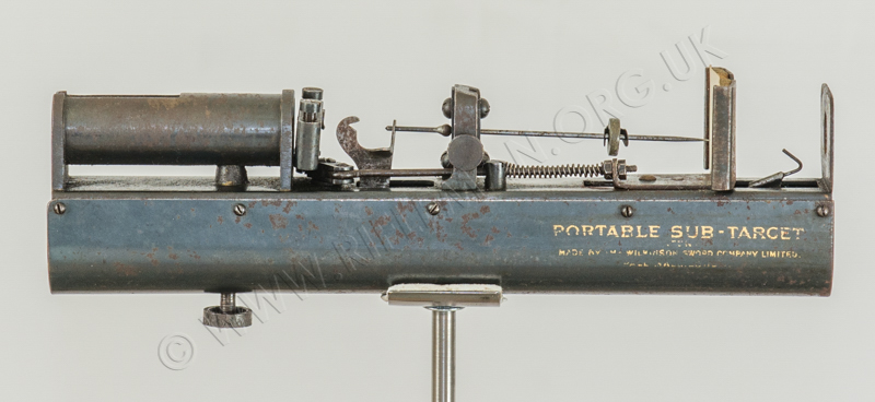
The Portable Sub-Target Machine
by the Wilkinson Sword Company
(circa 1900-1920)
See also: the Static WILKINSON SUB-TARGET MACHINE
It is presently uncertain what military service may have been seen by this apparatus, but there is nonetheless a sealed pattern example held in the old Enfield "Pattern Room" collection, now part of the Royal Armouries at Leeds. The pattern label indicates that the apparatus, "Sub-target, Portable, Mark I", was approved on the 15th. February 1911 under the reference 84-S-5656 and with approval number "LoC §15496"- (the War Office List of Changes of War Matériel), the tag being signed by A.S. Tisdall, the then Chief Inspector of Small Arms. A further note in red ink indicates obsolescence under the reference "LoC §23052", but without date; however, perusal of Skennerton's abridged volumes of the LoC affords a date for LoC §23051 between January and March 1920.
The tag gives a basic description of the equipment, and reads
"Consisting of a body, adapter (Rifles, Short, M.L.E., only,) axis tube, axis cord and winder, sub-target and stand, objective target. For musketry instruction, Rifles M.L.M., M.L.E., charger loading, M.L.E., and Short M.L.E."
The equipment shown in the first section of this page spent much of its life, until recently, in the store of the 32nd. / 61st. Surrey Home Guard Rifle Club. Its earlier history is unkown, but it is hoped that it will eventually be put on display in the N.R.A. Museum at the National Shooting Centre, Bisley, Surrey.
Should you hold any further information or literature on these devices, we would be most grateful to hear of it.
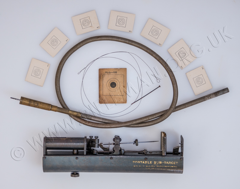
Below is shown the rifle attachment equipment, with hit registering targets, bore snake tube, a single aiming (objective) target of 10 yard equivalent to 600 yards range, a spare bore-tube connecting "axis wire", large pin for wire-loop connection, and the sub-target unit itself.
Below is a close up Rotatable and Zoomable view of the 8" long rifle attachment.
The hit registering needle carries an adjustable balance weight to assist with setting up.
It allows a fine balance of the needle to be obtained for best accuracy.
The next two images can be rotated and zoomed, either as initially loaded or full-screen for higher definition.
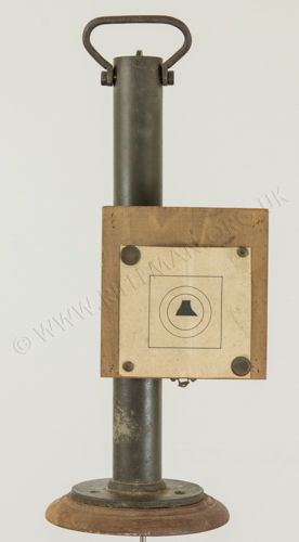
And a Rotate & Zoom view of the 20" high aiming target pedestal.
It is of solid brass, the tubular upright containing a counterweight that tensions
the 10 yard long connecting wire between the target pedestal and the rifle.
The figure target on the frame is believed to be an approximation of
200yds full size "First Class" Musketry target at a sub-target range of ten yards.
Below is shown the rifle attachment fitted to a "Long" Lee-Enfield, of which more later.

With the rifle's bolt removed, the flexible bore-tube is fed into the breech
until the dummy .303 cartridge case engages in the barrel's chamber.
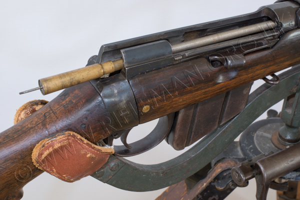
The spring-loaded "striker" can be seen protruding into the rifle's receiver.
When the re-fitted bolt is closed, this striker is pushed forward into the dummy cartridge,
but remains engaged with the parent rifle's own firing pin aperture in the bolt-head.

The thin wire that passes through the centre of the bore-tube has a loop in the end which must be looped over the hook in the end of the floating tensioner, or "axis bridge", the link bars of which pass beneath the hit-registering needle assembly. This rear end-hook of the axis bridge also engages with the rear of the needle. The forward end-hook of the axis bridge can be seen at the front of the unit on the right of the photograph. The ten to twenty yard tensioning axis cord to the target pedestal loops over this forward hook and completes the tensioning link between the rifle and the object/aiming target thirty to sixty feet distant. A large pin is provided to enable the fine axis wire and axis cord loops to be fitted over the hooks.
Once all the equipment is properly connected, tensioned and calibrated, using the adjustment screw on the needle support frame, any movement of the rifle, when in the aim, is transferred minutely to the needle, which should point to the sub-target at precisely the same point at which the rifle is aimed on the pedestal target that ten to twenty yards distant.

When the rifle's trigger is pulled, the forward movement of the bore-tube rotates the swivel mounted beneath the muzzle end of the barrel. This reversed rotation draws the spring-loaded sliding holder for the registering target rearwards, bringing the soft material backed target into contact with the needle. The action is almost instantaneous, and the target returns to its standby position, and the pin-hole is left to show the "point of impact", or the relative position in which a bullet strike would have been made.
This equipment is, frankly, quite fragile. It is not surprising that the rarity of these units suggests that take-up by the shooting fraternity was extremely limited, and that perhaps the survival rate was also rather low.
The nose-plate of the rifle attachment is simply marked
SUB-TARGET
CO. LTD
LONDON
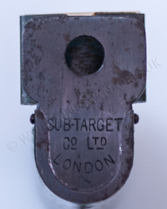
The Sub-Target Company was, in 1906, based at 27, Pall Mall in London. Stock Exchange records show that,
in August that year, the company was to acquire the sole rights for the manufacture and marketing
of the sub-target rifle machine throughout the whole of the British Empire (barring Canada), Siam, Egypt and Morocco.
A reference in the 1906-07 Sessional Papers of the Dominion of Canada mentions a request for paperwork
relating to the company's affairs which may relate to the rights for Canadian distribution of the device.
It states that "Return to an address of the House of Commons, dated 10th December, 1906, for a copy of all orders in council, contracts, reports of experts or officials, and of all correspondence relating to the adoption and purchase of 250 subtarget guns, by the department of militia, and especially all letters passing between the Ontario Sub-Target Company (Limited), Mr. J. H. Jewell, Mr. Hartley Devvart, K.C., or any director or shareholder of the Sub-Target Company, and the Minister of Militia, or his private secretary, in reference to purchases or contracts, or agreements to purchase, either proposed or consummated, and payments made thereon or in pursuance thereof. Presented 7th February."
An aiming target accompanying the sealed pattern of the machine in the Pattern Room collection,
carries the name of the Sub-Target Company at another address of 29a, Charing Cross Road, London;
of which details have yet to be discovered.
Below: the sight picture at the 200 yard equivalent target.
The limits of our photographic studio would not allow of even a ten yard range,
and the distance here is just under half that minimum norm.
It should be noted that the sub-target rifle attachment itself, along with the tiny hit registering sub-target,
is not visble when the "shooter" is in the aim.
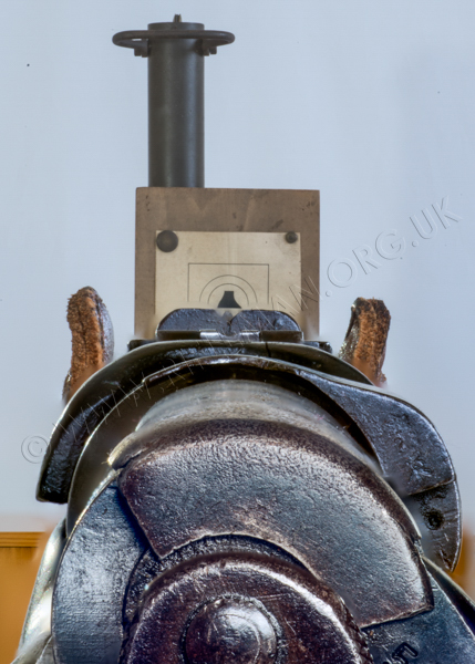
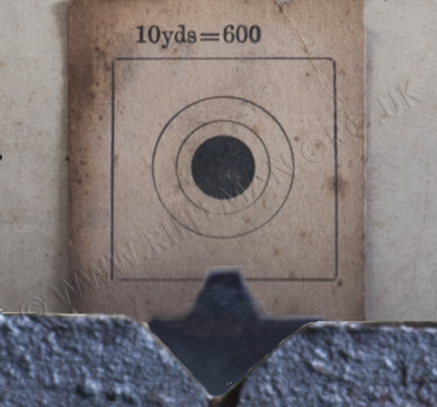
Again at half normal distance, the 600 yard target is shown with the 200 yard version.

Below: the sight picture of the 600yd target.
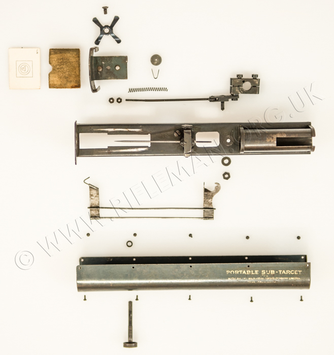
The rifle attachment was stripped for restorative cleaning, and photographed whilst disassembled.
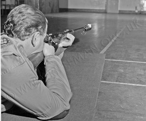
The following three monochrome photographs were probably taken in the 1960s period
when the members of the holding rifle club were trying out the equipment in a sports hall.
The distance between rifle and target pedestal appears to be more than the width of two badminton courts,
which, at 20 feet each, put the range on this occasion at near the twenty yards
that would suggest the use of a target such as that on the Pattern Room example of the pedestal - for "200 yards reduced to 20 yards".


The rifle on which the Sub-Target Machine is shown in colour on this page is a Magazine Lee-Enfield Mk.1*
manufactured by the Birmingham Small Arms & Metal Company in 1892, and marked "VR" for Victoria Regina.
Basic details are given in the following data datable, but more of this rifle can be seen via the link below.
The rifle in the black & white photographs is a similar, but possibly later, model.
This rifle is typical of the type that would have been used for training
with the portable sub-target machine during the first decade of the Twentieth Century.

DATA TABLE - ALL MEASUREMENTS AS VIEWED EXAMPLE |
||
FIREARM |
IMPERIAL |
(METRIC) |
| Designation or Type : | British Service Rifle
|
|
| Manufacturer : | Birmingham Small Arms & Metal Company |
|
| Date : | 1892 |
|
| Serial No : | 56810 |
|
| Furniture : | Walnut
|
|
| Action Type : | Turning bolt
|
|
| Nomenclature or main marks: | Magazine Lee-Enfield/Metford
|
|
| Calibre : | .303inch Centre Fire |
? mm |
| Weight : | 9 lbs. 4 ozs. |
? kgs |
| Length - Overall : | 49.25 inches |
? cms |
| Length - Barrel : | 30.375 inches |
? cms |
| Pull : | 13½inches |
? cms |
| Spare row : | - |
|
Rifling - No. of Grooves : |
7 |
|
| Rifling - Twist & Direction : | 1 turn in ? inches - RH |
? cms |
| Rifling - Groove width : | 0.0?? inches |
? mm |
| Rifling - Land width : | 0.0?? inches |
? mm |
Rifling - Groove depth at muzzle : |
||
| Sight - Fore : | barleycorn on block |
- |
| Sight - Rear : | V-notch tangent leaf |
- |
| Sight - Radius : | 21¾ inches |
? cms |
Below is the specially adapted 'Long' Lee-Metford Rifle used with the Static WILKINSON SUB-TARGET MACHINE
By kind permission of the trustees of the Pattern Room Collection at the Leeds Royal Armouries
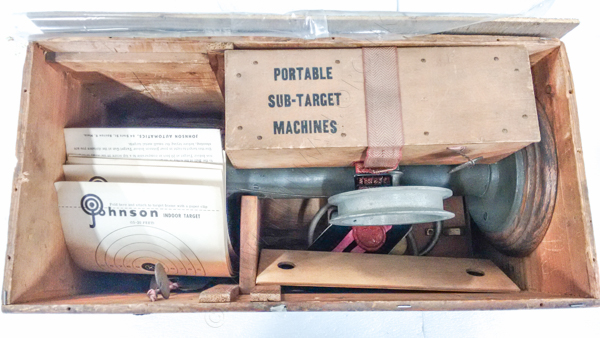
we are able to show some images of the sealed pattern example of the Portable Sub-Target Machine.
When fitted to the Rifle, Short, Magazine, Lee-Enfield (S.M.L.E.), the device requires an adapter.
This cast bracket effectively has the characteristics of the 1907 bayonet fixing at the rear (left),
which mounts on the SMLE bayonet lugs, and a false Long-Lee muzzle and fore-sight at the front -
to which the device attaches as if to a "Long" rifle.

The image below shows the arrangement when attached to a short rifle.

Another version of the portable machine is to be found in the collection of the Imperial War Museum in London.
This example appears to be more-or-less permanently attached to an rather fine especially modified S.M.L.E. Rifle No.1 Mk.III.
Unlike the Pattern example, with a separate mounting bracket for fitment to the short rifle,
this model has a different arrangement at the rear of the device.
A substantial plate, approximately 3/16" thick, is fixed towards the rear of the device.
This plate has a hole drilled in it to accommodate the especially extended muzzle of the SMLE barrel;
the plate abuts the SMLE nose-cap casting.
If the fore-sight area in the photograph looks unusual to those familiar with this casting,
it should be noted that the protector wings are covered with a
square shaped cover accessory of the type manufactured by A.G. Parker and Parker-Hale.
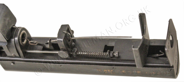
The other main components of the unit are ostensibly the same as the previously discussed detachable portable device.
Visible in the photograph above is the forward end of the axis wire that passes through the barrel inside the coiled wire tube.
The loop at the end of this rests over the rear hook of the axis bridge which runs inside the body of the unit to the front hook
onto which the axis cord that runs to the object target down-range would be looped.
The needle that punches the sub-target would normally be straight, but has probably been bent in storage.
The gold lettered transfer, in this case rather worn, is identical to that on the first device shown in this write-up.
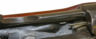
The "receiver" of the rifle is shown below, into which the extends rearwards from the chamber the pin which engages with the bolt-head,
and which is struck by the bolt's firing-pin, allowing the needle to run forward under pressure from the sprung pivot arrangement,
thus puncturing the sub-target. Note that the rifle retains its magazine cut-off plate above the redundant magazine platform.
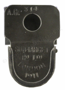
The nose-plate of this particular device again credits its production to the Sub-Target Company in London,
but adds a useful date to the stamping, along with the marks " A.G. - 314" the initials of which we have as yet been unable to identify, although there is an obvious potential link to A.G. Parker which may be purely coincidental.
"314" is quite possibly a unit serial number.
The above three images by courtesy of the Trustees of the Imperial War Museum.
The National Firearms Centre collection of the Royal Armouries in Leeds
holds the original Enfield Pattern Room Collection,
in which the Pattern example of the equipment is still kept.
Below: the storage box, with the pedestal, reel, rifle attachment and targets remain to this day.
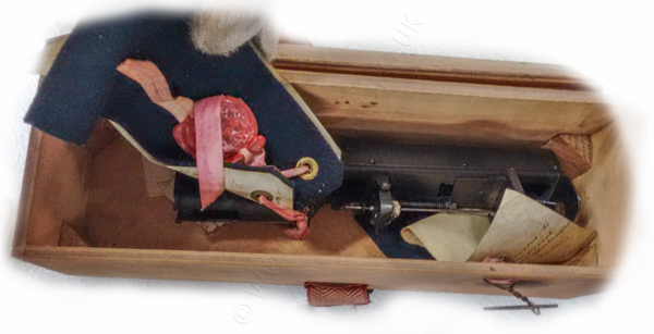
Below: the smaller box containing the rifle attachment,
which carries the wax seal confirming that the unit is the "Sealed Pattern" for the equipment.
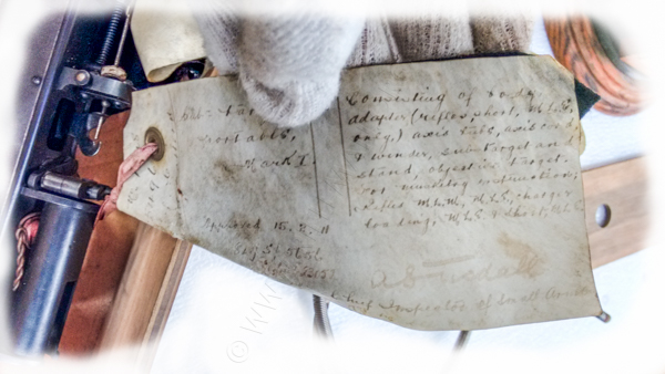
The label also attached to the unit has the handwritten notes stating on the left:-
"Sub-Target, Portable, Mark 1"
"Approved 15-2-11"
"84 / S / 5656"
..... and to the right, the text reads:-
"Consisting of a body adapter (Rifles,Short, M. L-E only), axis tube,
axis cord and winder, sub-target and stand, objective target.
For Musketry Instruction; Rifles M.L.M., M.L.E., Charger loading M.L.E. and Short M.L.E)." *
The label is signed "A.S. Tyndall, Chief Inspector of Small Arms."
* "M.L.M" refers to the Magazine Lee-Metford Rifle or 'Long" Lee-Metford.
"M.L.E" refers to the Magazine Lee-Enfield Rifle or 'Long" Lee-Enfield.
"Short, M.L.E" refers to the 'Rifle, Short, Magazine Lee-Enfield; (the S.M.L.E.)
" Charger-loading" irefers to the C.L.M.L.M. and C.L.M.L.E. rifles fitted with a bridge for loading from a clip of cartridges.
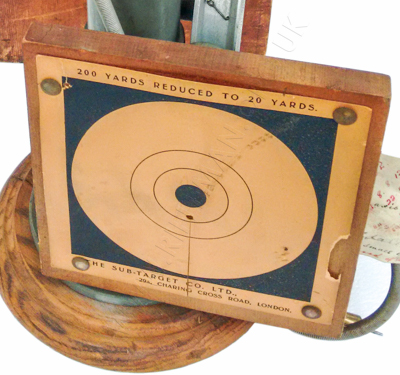
The pedestal is here stood in front of the box lid.

The target frame and target card attached to the pedestal,
show the scale as "200 YARDS REDUCED TO 20 YARDS".
The card is a company original, with the name and address printed on the bottom.
"THE SUB-TARGET Co. LTD.,"
"29A, CHARING CROSS ROAD, LONDON."
Below: the wooden board for keeping the 24 yard long silk axis cord for the 'winder'.

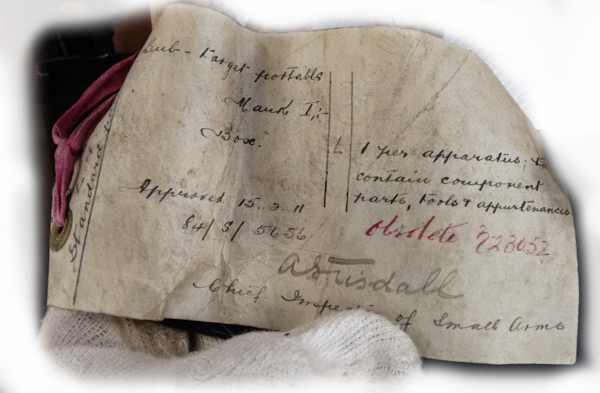
Even the adapter unit's box has a label bearing the same information to the left,
but adding the word "Box", with the text at the right reading :-
" 1 per apparatus: to contain component parts, tools and appurtenances".
In a different hand, and in red ink, the declaration of obsolescence is noted
as §23052 in the List of Changes, which dates to early 1920.
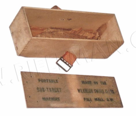
The box, with leather strap and loose lid bearing the Pall Mall address of the Wilkinson Sword Company.
An equivalent label is attached to the main storage box for the whole equipment,
but declared as "Case, Packing", with the same reference for obsolescence.

The above six images by courtesy of the Trustees of the Royal Armouries.
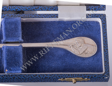
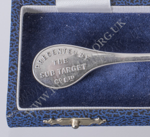
The Sub-Target Company even produced a silver presentation spoon,
presumably that could be awarded for competitions run using the system.
Such events would perhaps have been comparatively rare, and the spoon equally so.
Alternatively, the presentation may have been made to a purchaser of the equipment.
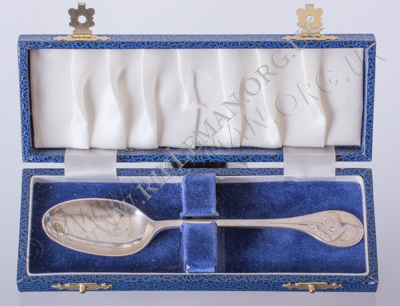
Below, left: the bowl has a target moulded into the tip and,
right: the stem bears a just distinguishable "wire" trace
leading from the militarily attired shooter using a "Long" Lee-Enfield rifle.
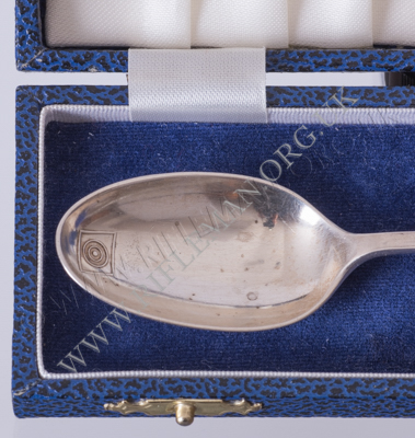 ...........................
The reverse of the stem-head carries the company's name and intended purpose of the spoon.
The 1911 dating of this device coincides with the first edition date of an instruction booklet held in the Pattern Room collection archives, and which we are pleased to be able to reproduce by kind permission of the Trustees of the Leeds Royal Armouries. That particular copy is a 1914 reprint with amendments, and the instructions relate to the fully portable model that can be used both with unmodified Long and Short Lee-Enfileld service rifles, by dint of the special adapter for the latter.
THE PORTABLE SUB-TARGET (MARK I)
AND HOW TO USE IT.
1911
REPRINTED WITH AMENDMENTS, 1914.

LONDON:
PRINTED UNDER THE AUTHORITY OF HIS MAJESTY'S STATIONERY OFFICE
BY HARRISON AND SONS, 46-47, ST. MARTIN'S LANE, W.C.,
PRINTERS IN ORDINARY TO HIS MAJESTY.
To be purchased, either directly or through any Bookseller, from
WYMAN AND SONS, LTD., 29, BREAMS BUILDINGS, FETTER LANE, E.C., and
64, ST, MARY STREET, CARDIFF ; or
H.M. STATIONERY OFFICE (SCOTTISH BRANCH), 28, FORTH STREET, EDINBURGH ; or
E. PONSONBY, LTD., 116, GRAFTON STREET, DUBLIN:
or from the Agencies in the British Colonies and Dependencies,
the United States of America and other Foreign Countries of
T. FISHER UNWIN, LONDON, W.C.
Price One Penny.
CONTENTS.
CHAPTER I.
PAGE
Description of the Portable Sub-Target... ... 3
Directions for Attaching :—
Magazine Lee-Enfield Rifle (Short) ... 5
Magazine Lee-Enfield Rifle, C.L. ... 7
Instructions of Detaching :—
Magazine Lee-Enfield (Short) ... 7
Magazine Lee-Enfield, C.L. ... 8
CHAPTER II.
A System of Exercises to be used in connection with
Portable Sub-Target, Mark I ... ... 8
Portable Sub-Target Practices ... ... 9
On the Range ... ... ... ... 10
CHAPTER III.
Instructions in the Care of the Portable Sub-Target,
(a 11249) Wt. 2553-720 7000 4/15 H & S P 14/418.
THE PORTABLE SUB-TARGET (MARK I),
AND HOW TO USE IT.
CHAPTER I.
The portable sub-target is an apparatus for use in conjunction with the magazine Lee-Enfield rifles (short and C.L.) for teaching the first principles of musketry, more particularly correct aiming and trigger pressing. It may also be used to illustrate the principles of adjusting sights, demonstrating the results of inaccuracy in aiming, aiming off, setting of wind-gauge, aiming up and down, and for several of the other purposes set out in the Musketry Regulations, Part I.
DESCRIPTION OF THE PORTABLE SUB-TARGET.
(See Fig. 1.)
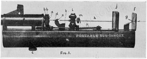
The portable sub-target consists of a body " n " having a socket " o " passed over the muzzle of the rifle, to which it is clamped by the set screw " c ".
A floating needle indicator " h " is supported upon an adjustable bearing at " l " and counterpoised by the movable weight " m ".
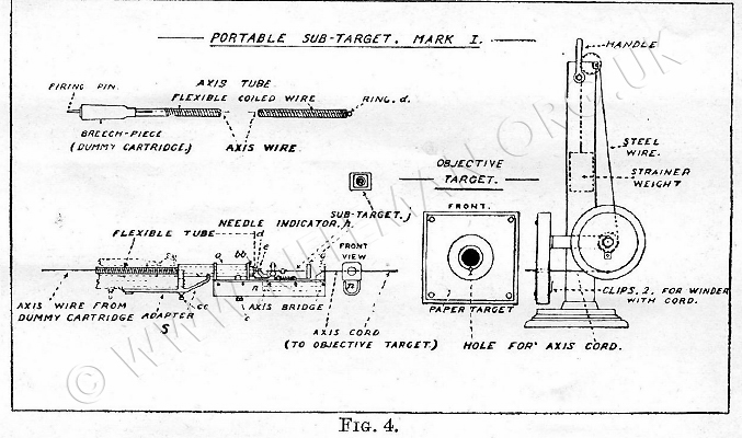
A dummy cartridge, shown in fig. 4, having a firing pin projecting into the striker hole in the bolt-head of the rifle, is prolonged by a flexible coiled-wire tube until it protrudes from the muzzle of the rifle into the split block " a " which is made fast to it by the two screws " bb ". Within the coiled tube is the axis wire terminating in the ring " d ". The split block " a " is connected with the sub-target " j " by means of a pivoted lever and rod " p ", around which a spring is coiled. When the trigger is pressed the striker actuates the coiled-wire tube within the barrel, forcing it and the split block " a " forward. This in turn pulls the lever and rod " p ", bringing the sub-target " j " into contact with the point of the needle indicator " h ", whence it receives an indentation corresponding with the point of aim on the distant target. When the rifle is cocked the spring on the rod " p " retracts the sub-target " j " and releases the needle indicator.
From the distant objective target is stretched a silk cord, the axis cord, which passes through the hole in the plate " f " and is attached, by means of a loop made in the axis cord for the purpose, to the hook " g ". The hook " g " is connected with the hook " e " by the axis bridge within the body " n ". The axis cord is then continued through the ring " d " to the axis wire in the centre of the bore of the rifle.
The distant end of the axis cord passes through the objective target, and is coiled round a wheel with which is connected a suspended weight, by which it is kept constantly in tension whilst in use.
The underlying principle of the apparatus is the continuation of the axis of the bore (or line of departure) to the distant objective target, and a connection between the axis of the bore and line of sight made at the link " k ", whereby the relative position of the line of sight and axis of the bore is indicated by the needle " h ", and recorded upon the sub-target " j " when the trigger is pressed. In effect the indicator needle always points to the distant target, whilst the sub-target moves with the rifle.
The motions of the rifle are magnified by the needle indicator, in the same relative proportions as the sub-target bears to the distant objective target. The indicator needle may be adjusted to move in exact harmony with the sights within certain limits, vertically by moving the counterweight " m " forwards or backwards, and laterally by turning the screw " r ". Once approximately set to agree with the sighting the groups made by the needle upon the sub-target may be centred by adjusting the sights precisely as is done when applying fire on the range.
DIRECTIONS FOR ATTACHING.
(See Fig. 2.)
Magazine Lee-Enfield Rifle (Short).

Attach the muzzle adapter " s " to the muzzle and fix by set-screw " cc ".
Remove the bolt and take extractor off bolt-head.
See the inside of bore is clean.
Pass the coiled-wire tube and dummy cartridge into the barrel from the breech end, holding the muzzle downwards ; replace and close bolt, leaving the rifle cocked. The ring "d" at the end of the axis wire should now be seen protruding from the muzzle. The coiled wire should under no circumstances be stretched.
Should the coiled-wire tube containing the axis cord, when pressed downwards from the muzzle, be found to recede into the barrel, it indicates that the firing pin has not entered the striker hole in the bolt-head, in which case the bolt must be opened and closed again, when the firing pin should seat itself properly.
Slip the body on the adapter, passing the protruding end of the coiled tube containing the axis cord through the split block " a " up to the stop, and tighten the screws " bb ". Pass the ring " d " at the end of the axis wire over the hook " e ".
Before finally fixing the body to the rifle by tightening the set screw " c " it is necessary to find the correct position by pressing the split block " a' down into contact with the face of the muzzle, with the finger at the same time sliding the body upwards as far as may be necessary in order to set the lever at an angle to the block.
Place the objective target (see fig. 4) in the desired position at any distance between 10 and 20 yards from the rifle. The axis cord will be found with one end attached to the target and the other wound round a winder. Unwind as much as may be necessary to reach within 2 feet of the muzzle of the rifle. Make a loop in the cord, pass it through the hole in the plate " f " on the body and over the hook " g ".
The objective and sub-targets issued with the portable sub-target are prepared to a scale appropriate to 20 yards.
The wheel device on the objective target is designed to minimize the possibility of breaking the axis cord and to keep it taut. It is only intended to afford a stretching latitude of a few feet, and is not for winding the axis cord for storage. Normally there should be 6 coils of the axis cord about the wheel when at rest.
Step backwards with the rifle until the axis cord is taut, but not stretched to its extreme limit, and keep taut during practice.
The loose winder carrying the superfluous axis cord must be tied to the piling swivel or allowed to rest upon the floor. On no account must its weight be allowed to hang upon the axis cord or it will falsify the registration of results.
The portable sub-target cannot be used if exposed to a strong wind, and whenever used outdoors should be placed so that the rifle points into the wind.
When adjusting the apparatus with the rifle sights the object is to bring the axis cord fairly central in the hole in the plate " f " when correct aim is taken.
If when correctly adjusted the needle indicator persistently groups its hits elsewhere than in the centre of the sub-target, it is due to some aiming or holding peculiarity of the user, which should be corrected by appropriate adjustment of the rifle sights.
Magazine Lee-Enfield Rifle, C.L.
(See Figs. 1 & 3.)

In attaching the apparatus to this pattern rifle, the adapter is not used, and the sight protector and screw must first be removed.
Other wise the above method should be employed.
INSTRUCTIONS FOR DETACHING.
Magazine Lee-Enfield (Short).
Unhook axis cord from hook " g ".
Rewind cord on winder.
Unhook axis wire ring " d ",from hook " e ".
Loosen screws " bb ".
Loosen screw " c ".
Loosen adapter fixing screw and remove adapter and
apparatus from nose cap.
Remove bolt, replace extractor.
Draw out dummy cartridge and coiled-wire tube.
Magazine Lee-Enfield, C.L.
As above, but omitting the removal of the adapter.
IMPORTANT.
An apparatus of this kind is necessarily delicate and fragile, and must at all times be used and handled with great care. The axis cord being very inconspicuous, it is advisable when the apparatus is in use to interpose some obstacle to prevent any person crossing the line of fire and breaking the axis cord. It is a good plan to set rip the apparatus close to and parallel with a wall.
A sandbag or similar support should be placed in front of the firer so that the rifle when not in use may be rested on it. Possible damage to the body and the adapter is thereby avoided.
CHAPTER II.
A SYSTEM OF EXERCISES TO BE USED IN CONNECTION
WITH PORTABLE SUB-TARGET, MARK I.
The portable sub-target is primarily of value for the purpose of developing the aiming and trigger pressing faculties. It may also be used with advantage for demonstrating other principles of aiming set out in the Musketry Regulations, Part I.
The fundamental basis of musketry is the development of those human faculties by which the rifle is aimed correctly and discharged without altering the aim. The tactical and theoretical side of musketry, viz., estimation of distance, knowledge of trajectory, adjustment of sights, allowance for moving objects, for wind and other natural phenomena which affect the flight of the bullet, may be inculcated by lectures and by practice upon the range and in the field, but only successfully when the first principles have been so acquired that a perfect aim and let off have become an intuitive habit.
It is desirable that a system of instruction, whereby the portable sub-target may be utilized to the best advantage with due appreciation of its legitimate purpose, should be laid down.
An elementary bull's-eye target will be used in practices Nos. 1 and 2, and a regulation figure target in practices Nos. 3 and 4.
A fairly steady needle indicates steady holding. A jerky let off is shown by the needle jumping at the instant of discharge.
It is undesirable to continue any practice so long as to fatigue the recruit and cause a loss of interest.
PORTABLE SUB-TARGET PRACTICES.
1st Practice.—Object to test holding, and develop trigger pressing. Positions prone and kneeling.
The instructor will note the movements of the needle indicator at the instant of discharge entirely with regard to its steadiness, and without reference to accuracy of aim.
In this practice the point of impact on the sub-target is immaterial.
This and subsequent practices may be continued ad lib., gradually increasing the speed until the trigger is pressed 10 times a minute with perfect steadiness.
2nd Practice.—Object. Aiming and trigger pressing combined. Prone and kneeling. The test of skill in this practice will be the dimensions of the group embracing 5 shots. The sights need not be adjusted to centre the group.
A normal recruit should make a 3/5th inch group, a trained soldier a 5th inch group, and a marksman a l/5th inch group.
Daily exercise in this practice will be found advantageous for trained soldiers as well as recruits.
Practice 3 (a).—Application practice. A sighting shot followed by 5 shots to count. The recruit should be encouraged to reckon his own scoring and correct his sighting himself. The instructor should confine himself to verbal explanation. He should under no circumstances alter the man's sights.
Practice 3 (b).—Object. Aiming off. Repeat 3(a), but with the sight set to one side so that the firer will have to aim off in order to group in the bull's-eye. Alteration of the sights by the firer not allowed.
Practice 4.—Object. A rapid and steady manipulation of the bolt combined with accuracy of aim. Regulation figure target. Two sighting shots will be taken. The sight will be altered only after the first. One minute will now be allowed to fire as many shots as possible combined with the greatest accuracy.
Practice 5.—Object. To provide amusement and competition under difficult conditions. The apparatus will be arranged in the open, where a side wind is blowing on the axis cord or in the direction of the setting sun, or both, and practices Nos. 3 (a) and 3 (b) repeated.
ON THE RANGE.
When ball practice is in progress the portable sub-target may be taken to the range and set up in a sheltered spot.
When a soldier is shooting eratically the cause, if personal, may generally be diagnosed with the aid of the apparatus, and, if found to be due to unsteady trigger pressing or imperfect aiming, a series of 20 or 30 shots with the apparatus will generally improve matters so considerably that the soldier may renew cartridge firing immediately with advantage. If the fault is found to be due to flinching from noise and recoil, ball firing should not be continued.
CHAPTER III.
INSTRUCTIONS IN THE CARE OF THE PORTABLE SUB-TARGET, MARK I.
- Care must be taken that the silk axis cord, before being attached to the axis bridge, is not twisted, so as to ensure that the axis bridge hangs in a vertical position.
- The breech-piece firing pin should be occasionally oiled.
- The flexible tube should be occasionally wiped with a. slightly oiled cloth ; care being taken that no excess of oil is allowed to remain on the face of the coil, as this would tend to lengthen the tube.
- All oil should be removed from the bore of the rifle before inserting the tube.
- To insert a new axis wire—
The breech end of the axis wire is attached by a small hook to the breech piece. In the event of a breakage of the axis wire, the new axis wire should be passed down the axis tube from the muzzle end and drawn out through the slot of the inner tube of the breech piece, and the loop attached to the small hook which also falls through the same slot.
In tubes of later manufacture where the breech piece is screwed on to the rear end of the tube and the axis wire is attached to a hooded hook in the breech piece, the following instructions will be observed in replacing a broken axis wire :—
Unscrew breech piece from axis tube, raise hood, detach broken axis wire (if necessary), attach new axis wire, close hood, pass axis wire through axis tube, and screw home breech piece.
That the device was accepted to be satisfactory for adotion by the militarty is evidenced by a report produced by the Experimental Officer at the Hythe School of Musketry in November 1909, here shown in facsimile.
REPORT on the JUNIOR SUB-TARGET
and CHEYLESMORE TARGET PRACTICE ROD*
Reference: W.O. paper 84/S/5593
The Junior Sub-Target has proved entirely reliable and is much liked. Since it was shown at the N.R.A. meeting at Bisley the Bowden type wire connection has been done away with and a brass rod passing down the bore substituted. This is centred in the chamber by means of a dummy with the base filed off and,as at present arranged, this entails the removal of the extractor.
It is also necessary to remove the foresight protector. A steel pin which, when the bolt is close, enters the striker-hole in the bolt-head, makes connection between the striker and the axial wire. It is not thought that this can cause any damage to the rifle.
Various sized aiming marks are provided, and the cord connecting the needle with the target can be adjusted to any length desired so that it is not necessary to work at any fixed range, as is the case with the Sub-Target Machine. A distance of 20 yards appears to be the normal, as at that distance a shot aimed at the edge of the target causes the needle to strike the edge of the sub-target.
The needle is sensitive but it is found that it will give an accurate record up to a rate of 15 rounds a minute and in some cases more.
The mechanism is not likely to be injured by reasonable use and the apparatus seems likely to be of great value for barrack room instruction and in cases where funds do not permit of a Sub-Target Machine being bought.
An adapter is provided which enables the apparatus to be used with the S.M.L.E. as well as with the L.E rifle.
In view of the S.E.E’s opinion (S.A.C. minute 100.1) that manufacturing cost would be small, the price of seven guineas does not seem excessive.
The Cheylesmore Rod is on the same principle as the Hollifield rod reported on in 84/H/4298, but is not in two parts. One long rod extends from the breech to muzzle and is surrounded by a spiral spring. At the muzzle is a brass plug which centres the rod in the bore. The rear end of the rod is struck by the striker on the trigger being pressed and the rod is then thrown forward so that it projects from the muzzle. At the muzzle end of it is a boss carrying a needlepoint and this impinges on the target and makes the record. A weak spiral spring then draws the rod back into the barrel.
It is found that if the muzzle of the rifle is more than about ten inches from the target the record made is not reliable. This might be remedied by making the rod stiffer and lengthening the bearing in the muzzle plug.
If however the rifle is held sufficiently close to the target to get a reliable record it is found that the boss at the end of the rod strikes the target so hard that it is liable to tear it and that it also obliterates the puncture of the previous shot. The rubber pad at the end of the Hollifield rod was not open to this objection. The needle point is much too coarse and should be cylindrical rather than conical.
The nick cut in the circumference of the cardboard target allows the target to move in its holder, and its position is likely to vary from shot to shot. The type of target which has three small triangular nicks in place of the one large one is much superior. A specimen of each kind of target is attached.
(Lt.) G. Browne
Capt, Experimental Officer, Hythe School of Musketry,
2/11/09
Report transmitted to D.G.D. 4/11
Commandant concurs, and considers
The Sub-Target worth adoption, the other not.
Instructions asked for disposal of unit.
* The Cheylesmore Target Practice Rod was marketed by W.W. Greener
and advertised in the Greener catalogue of 1914 on page 58 of the PDF.
See also: the Static WILKINSON SUB-TARGET MACHINE
Return to: TOP of PAGE
See this website's Raison d'être
