The imagery on this page when printed out should permit a capable constructor
to scale off the necessary dimensions from the basic ones given
to make an acceptable operational replica,
if used in conjunction with the images already on the main page and its links for the rifles and accessories.
___________________
Here is the initial patent application of October 1941 for the Swift target frame..
There was a second application in February 1943
SWIFT TRAINING RIFLE COMPANY Ltd.
Applicants: .....ZYGMUNT DE LUBICZ, BAKANOWSKI;
FREDERICK JOHN, MINNS;
GARNET WILFRED GLOVER, NORMAN
Improvements in or relating to target carrying stands and target frames carried thereon
TARGET CARRIERS
A collapsable target-carrying stand for use with a dummy rifle 35, which is fully connected by a yoke 36 to the stand, comprises two uprights 10, 101 connected by cross-bars 11, 12, 13. The uprights are grooved at 14, 15 to receive and hold frictionally a target frame 16, Fig. 4, the uprights of which carry bolts 17 which project through slots 18 in the uprights and whereby the frame can be clamped in any vertical position on the stand. The yoke 36 is also hinged on the bolts 17. The lower cross-bar 13 rests in notches in the converging side-bars 20, 21 of a base frame, and is clamped thereto by a bolt and nut 29. A hinged stay 25 is connected by a bolt and nut 28 to the cross-bar 12 of the stand. When the bolts 28, 29 are released, the uprights 10, 101 and parts carried thereby may be laid flat on the base and clamped thereto by another bolt and nut. The dummy rifle is connected to the yoke by a hook 38 which is passed over a reduced part 50 of the yoke cross-bar. The top and bottom bars of the target frame 16 are grooved at 30, 31, Fig. 4, to receive strips 32, 33 carrying clips 34. The target is hooked on to studs 5, 6 on the top bar and the edges of the target are bent over the grooves 30, 31 and pressed thereinto by the strips 32, 33. The base is supported upon rollers.
_______________________
Here follow the first twelve images of our fairly accurate replication of an original.
They can be zoomed in significantly to allow close inspection of the assembly.
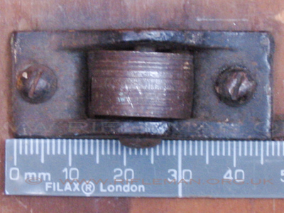
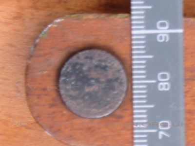
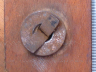
The second batch of images are of the various parts of an original frame,
and most have a scale included in the photograph.
Click images to bring up hi-res file and magnifier
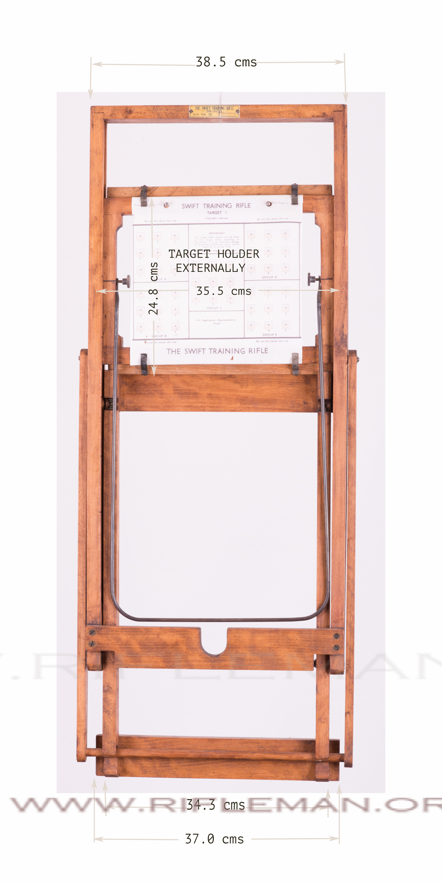
When folded for transport, the angled support arms swing right forward over the main frame
and locate in the spare pair of retaining slots at the front of the base frame.
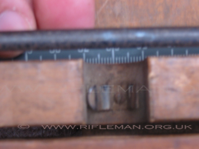
The target holder is then dropped from a high position until
the lower of the two small boards,
which carry the 'Terry' clips to hold the target onto the holder,
locate in two small recesses in the base frame
to prevent it from swinging out of its storage position.

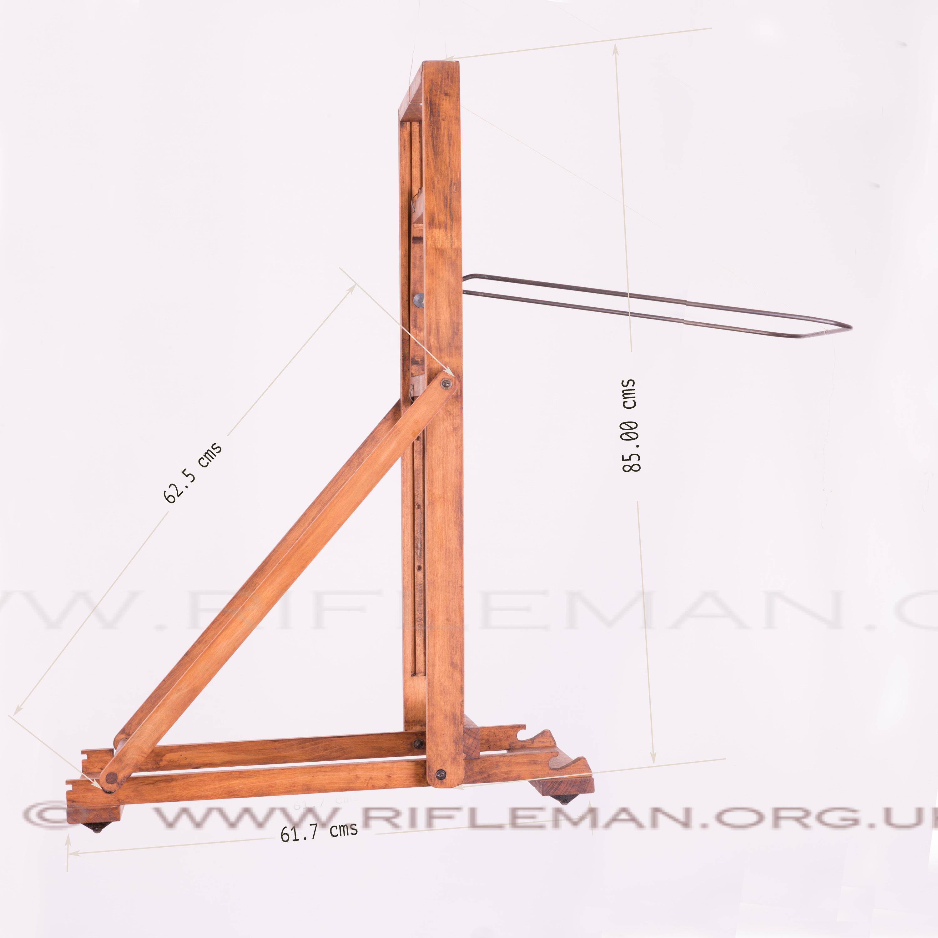
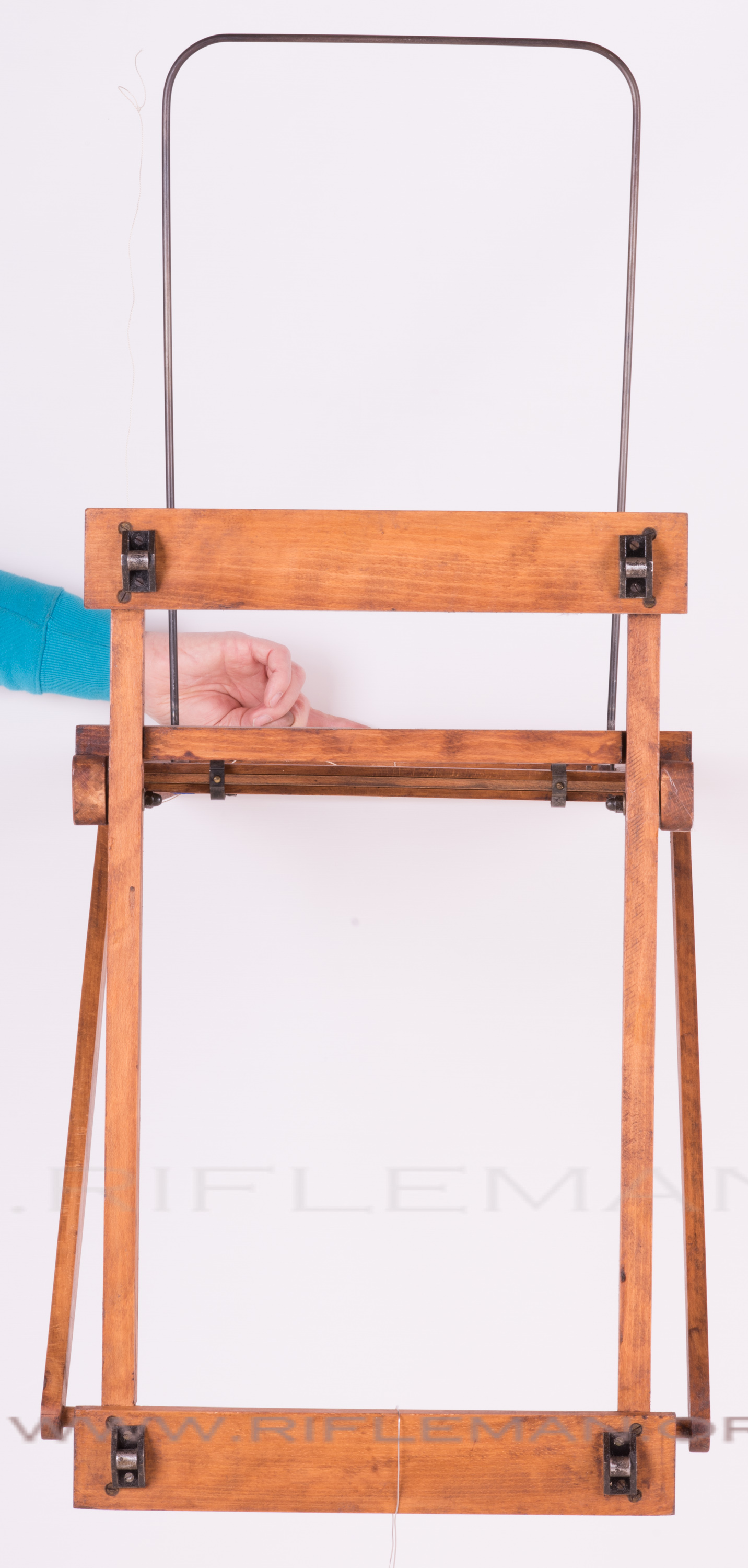
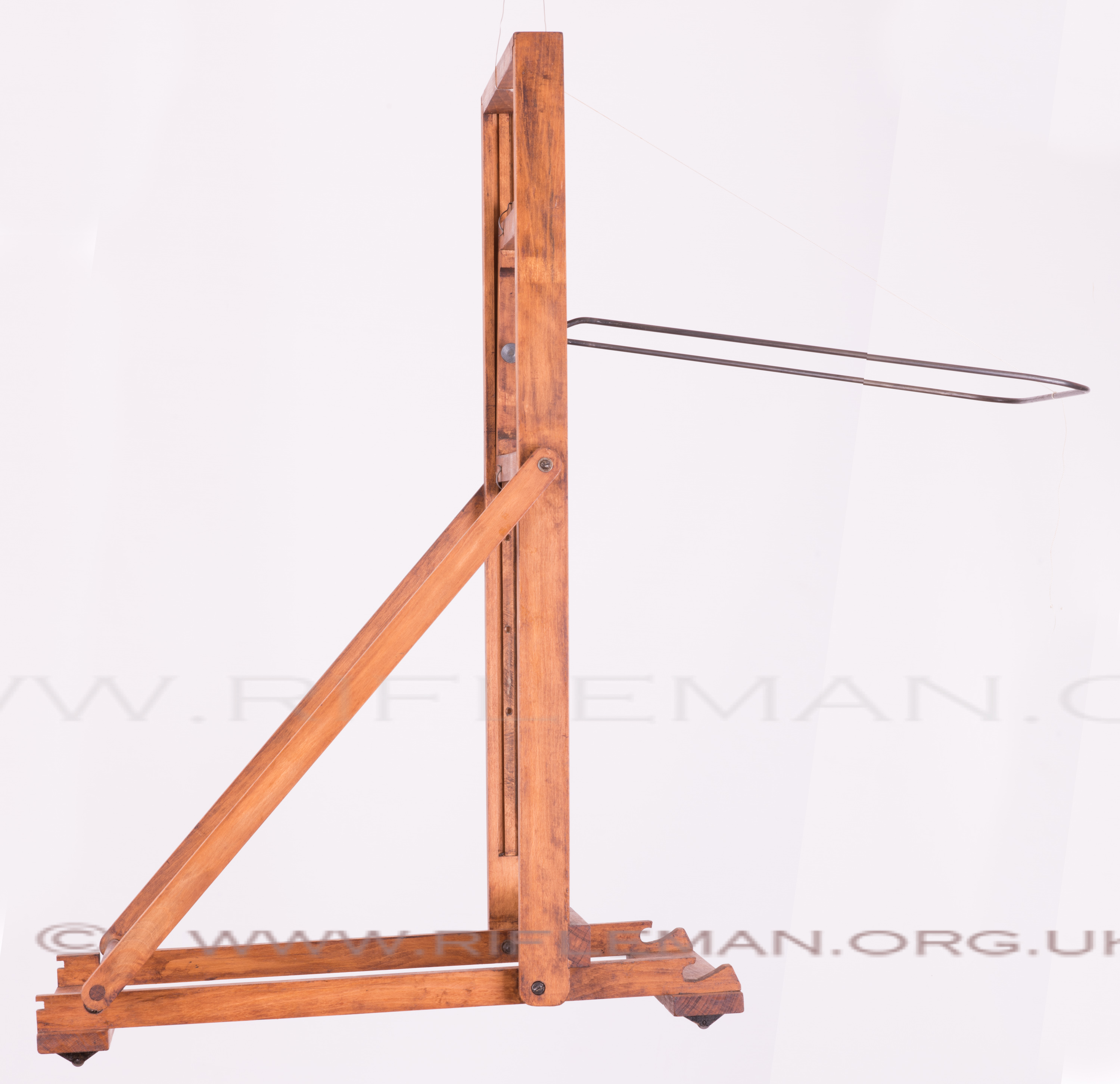
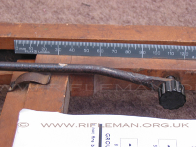
The two knurled knobs holding the steel rod bridle
(to which the rifle clips to maintain the correct distance of the muzzle to the paper target)
screw into a series of holes, in the channel on the inside of each vertical of the main frame,
dictating the vertical position of the target holder.
This allows the rifle to be used prone or kneeling when the frame is on the floor,
or standing if the frame is stood on a table.
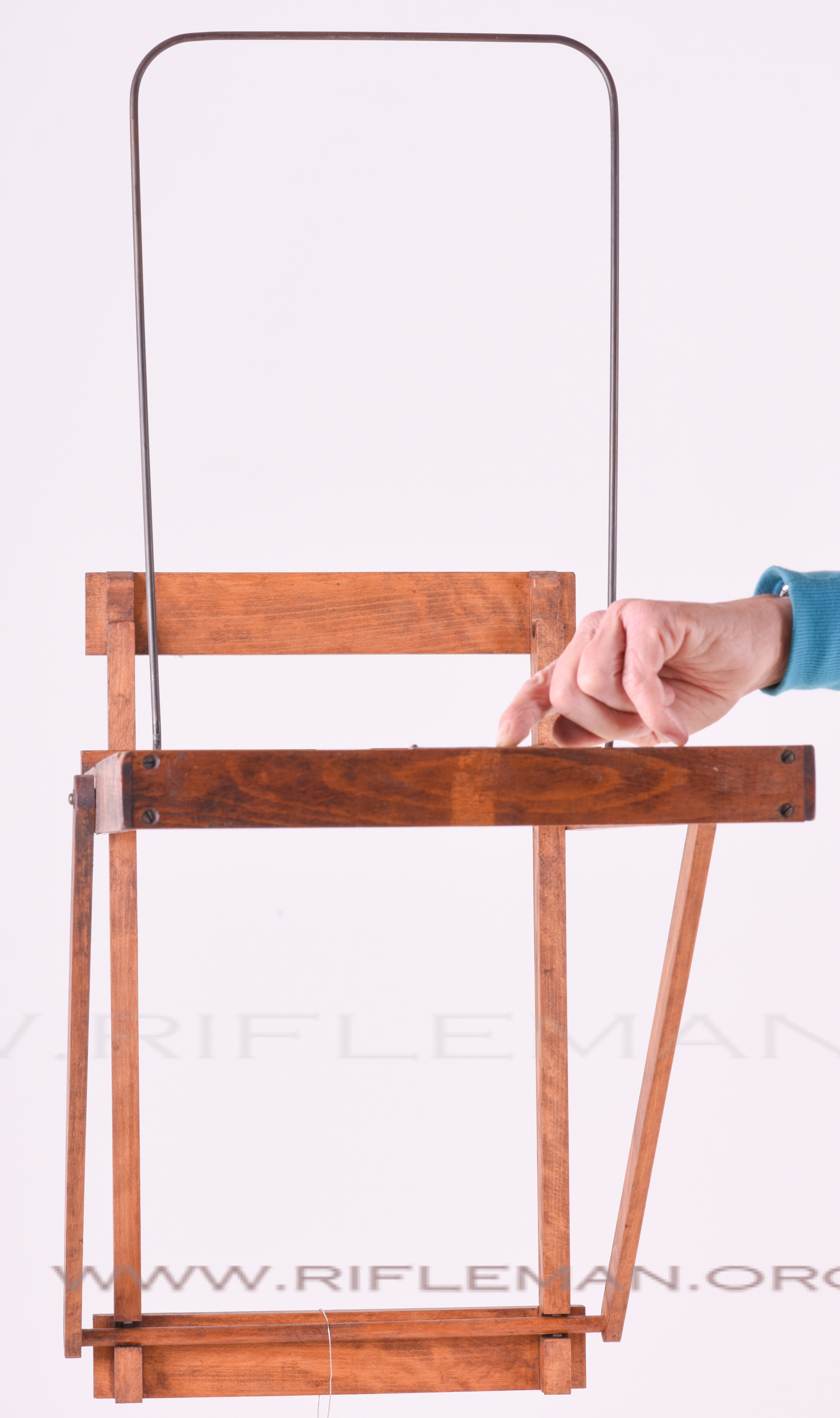
The target retaining board and its clips are show resting on top of the holder,
which has slots top and bottom to accommodate the board
and two thicknesses of the paper target.
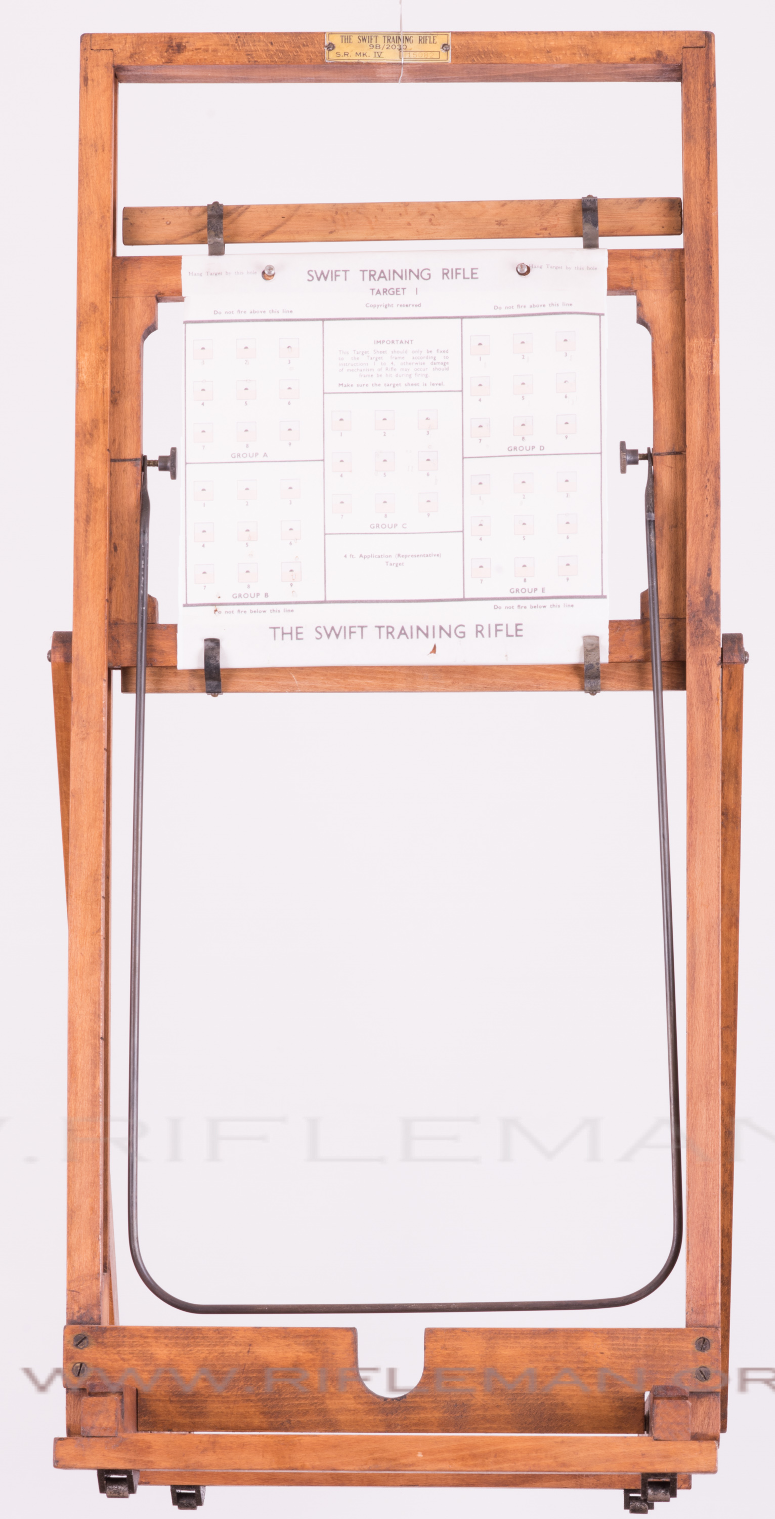
The "U" cut-out in the bottom board of the main frame is for resting the rifle.
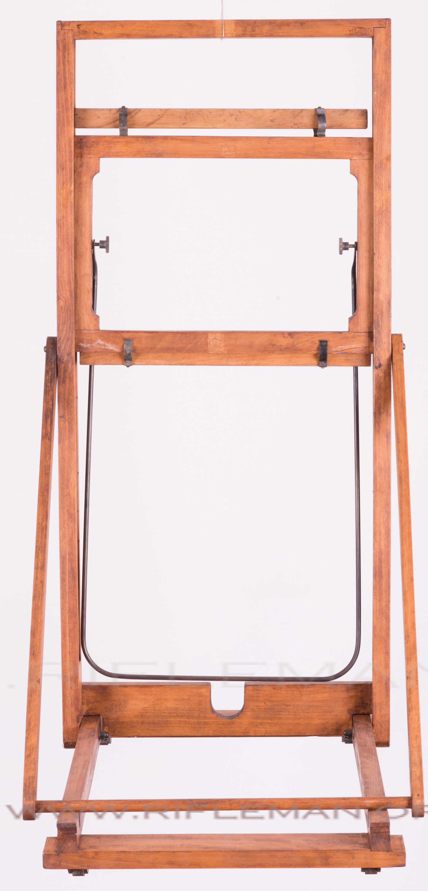
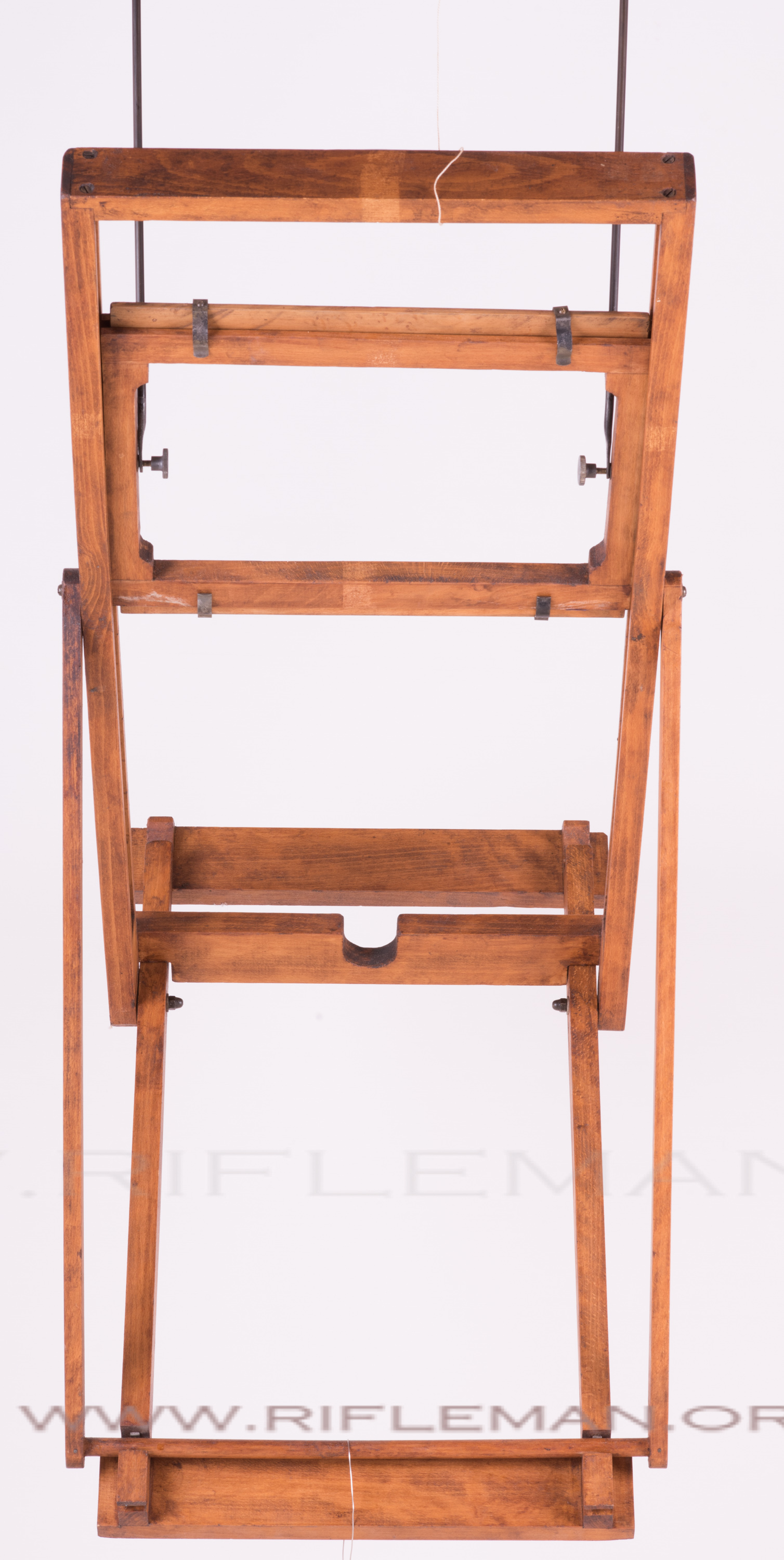

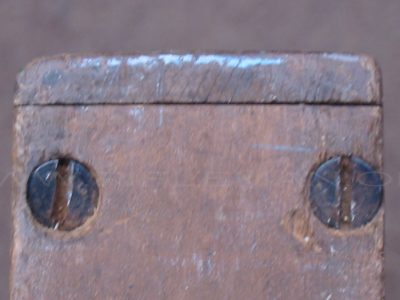
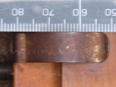
Note the small cut-outs at the rear of the base frame, bottom right in the image below,
into which the edge of the lower thin target-holding board with the spring clips
locate when the whole frame is folded for storage and transport.
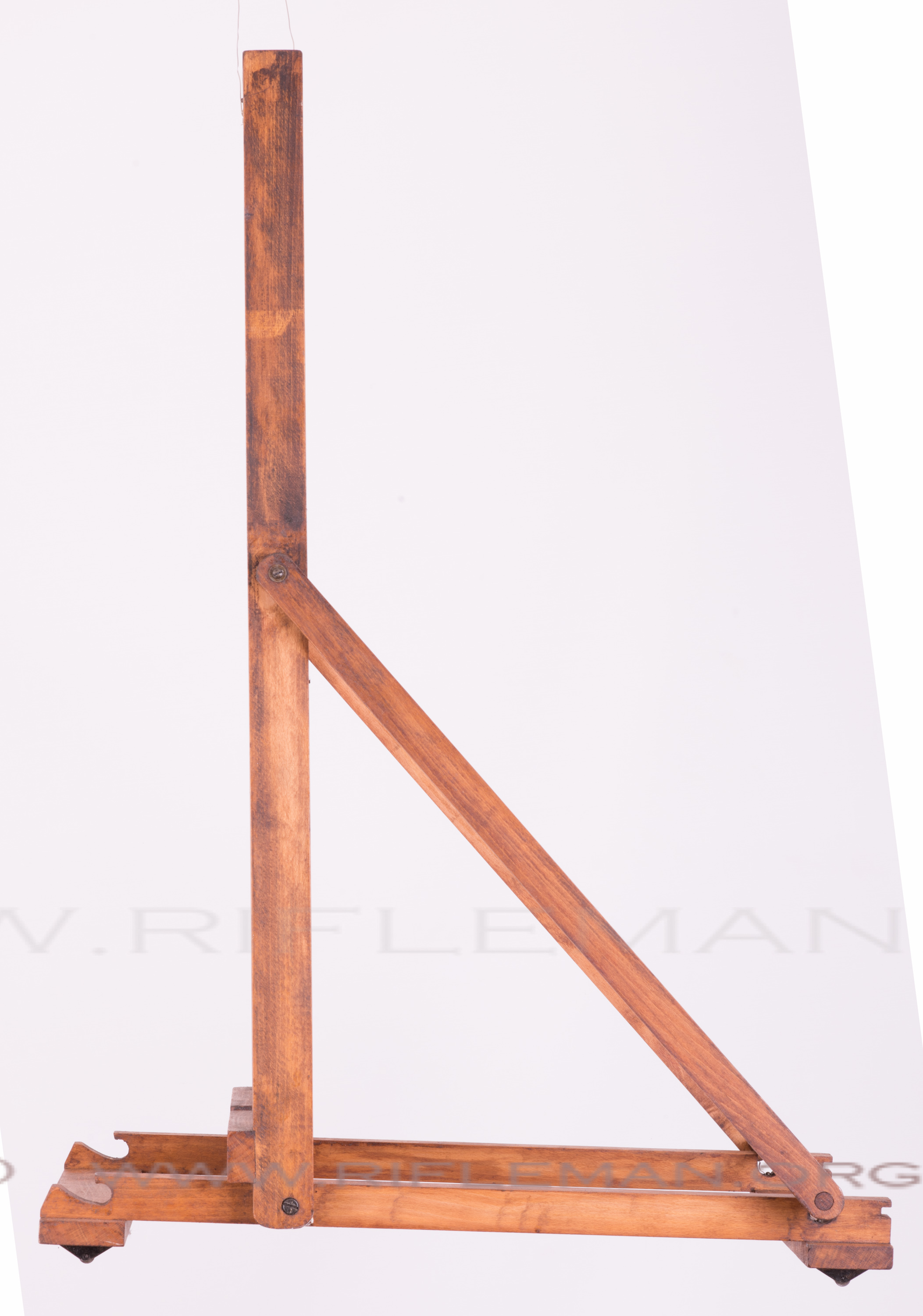
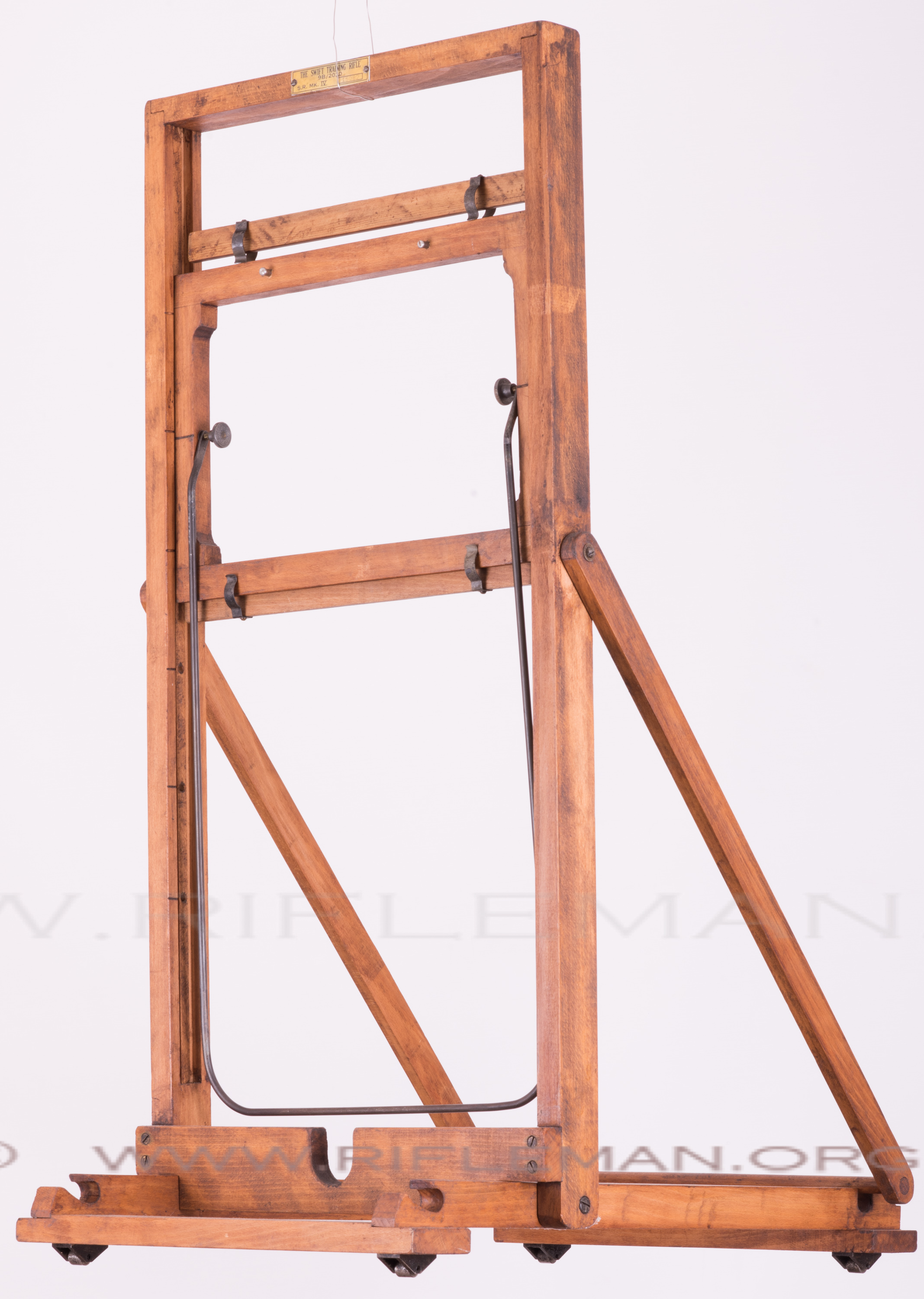
THE ORIGINAL FRAME FOR THE "B" SERIES RIFLES
The rollers are necessary to allow the frame to move back and forth
on what needs to be a smooth flat, floor or table.
This ensures that the "shooter" can position himself with the rifle,
and the frame and target will move into their correct position
in relation to the trainee.
 ...............
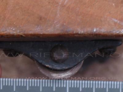
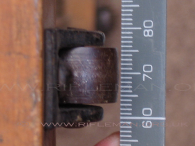
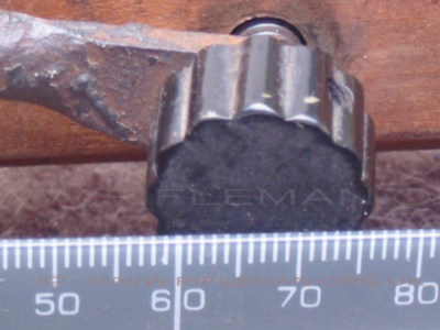
The original wheel supports were cast items.
Those on our replica are machined.
 ............
 .............
 ..........
The target holder thein "boards" and the original Terry clips.
 .............
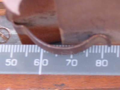
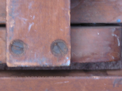
Note the Terry clips in the recesses at the rear of the base frame,
to hold the cross-dowel between the two angled support arms
when they are in position holding the framework for use.
 .............
Should you have any queries during construction, feel free to make contact.
GOOD LUCK