
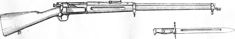
The Krag rifles were of Norwegian design, and issued both there, Sweden, and in Denmark as service weapons. The design was also licensed for production in the U.S.A., and became their main service rifle in .30-40 calibre as the Model 1892-99, manufactured at the "Springfield Armory" up until 1903.
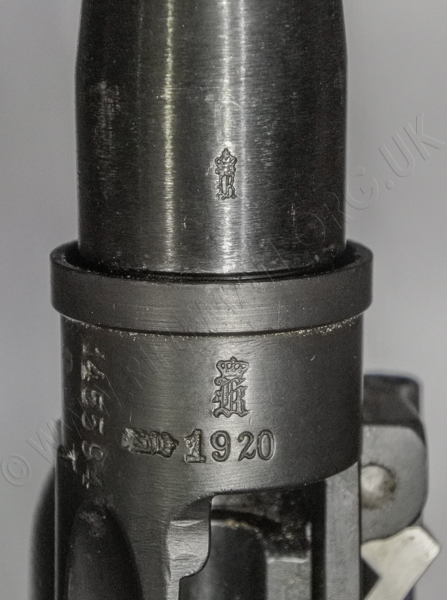
The example shown on this page is a converted Swedish service rifle manufactured in 1920.
The earliest associate patent covering the sliding breech block design was the 1889 no. 18,430 by P. Jensen, in conjunction with Norwegians O.H.J. Krag and E.J. Jörgensen. Ole Krag was a director of the Kongsberg Våpenfabrikk arms manufactory, and Eric Jörgensen was a professional gunsmith.
The various patents are shown in a searchable PDF further down this page.
In fact, Denmark was the first country to issue the rifle to its forces in 1889, in 8 x 58Rmm calibre, and the arm was serving in Scandinavia when Germany invaded in 1940. Norway later adopted the rifle in 6.5 x 55mm calibre - that of the fine Swedish 1896 Mauser. The barrel was therefore of a comparatively small bore by contemporary standards, and provided a particularly flat trajectory that made range assessment to a target less critical than other rifles of the day. The Krags remained in service until the cessation of the Second World War in 1945.
THE RIFLE
Drag horizontally to rotate subject - Click to zoom and drag to pan - Full screen viewing from expansion arrows.
A similar gallery practice rifle was also converted from the Model 1898 rifle,
and the Stevens Arms Co., even made a "Little Krag" for boys.
See also: Stevens single-shot rifles in British hands.
________________________
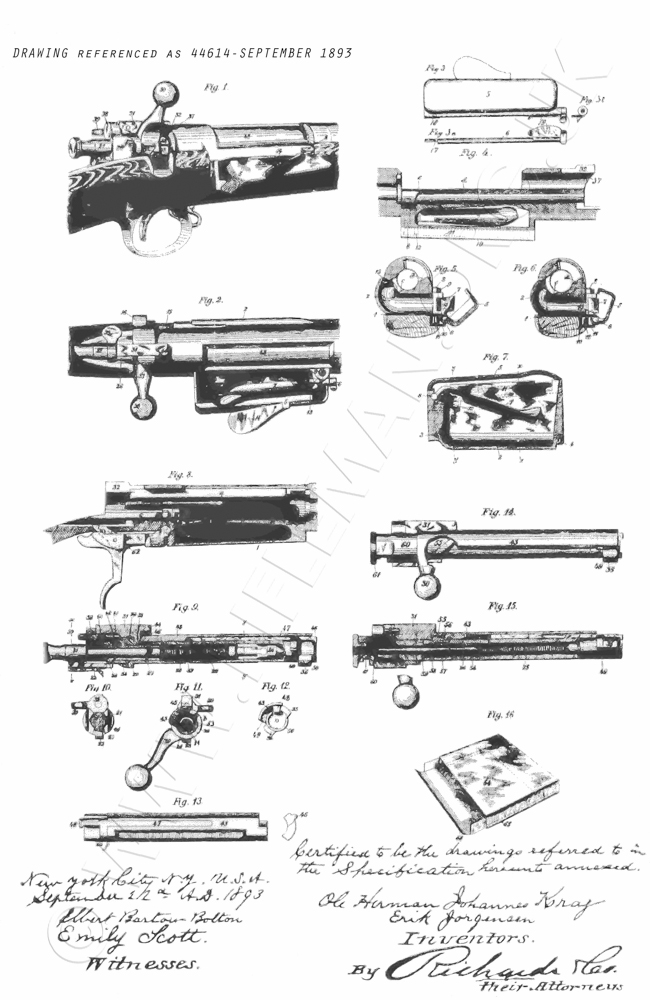
The Krag-Jörgensen Patent Applications and Drawings.
First application was on 10th. June 1890
--------
Then, mentioned in the text of the latter application is their following application
No. 437,097 of 17th. June 1892.
----------
The main patent application was no. 492,212 of 21st. February 1893.
 ...
...
But an additional drawing, referenced 44614, was submitted in September of 1893.
This included almost all of those sections shown separately in the February application,
but on one sheet. It is difficult to assess whether any parts were amended.
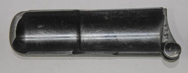
The rifle disassembled

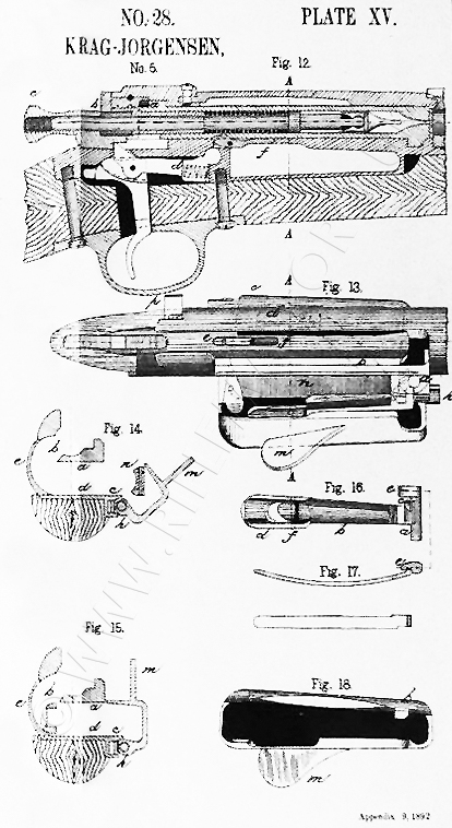
Below: an 1892 drawing of the action from the appendix of a contemporary Ordnance Manual
The description and drawings of the Danish Krag
extracted from the HMSO Text Book for Smallarms of 1909
These text-searchable documents can be viewed with vertical scrolling
or as flip-pages by clicking the appropriate icon where shown.
Depending upon the number of pages they may take a few moments to load.
Double tap tablet or click ![]() for full page display.
for full page display.
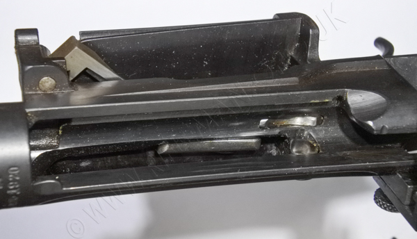
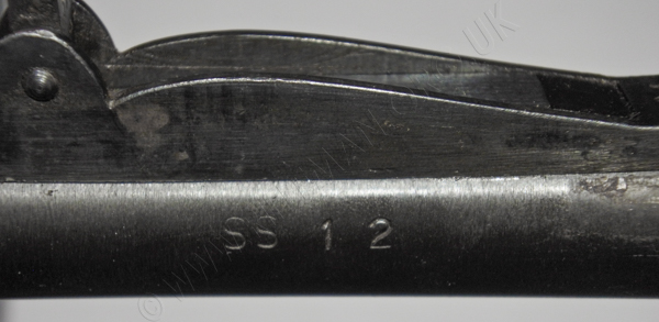
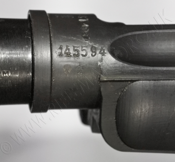
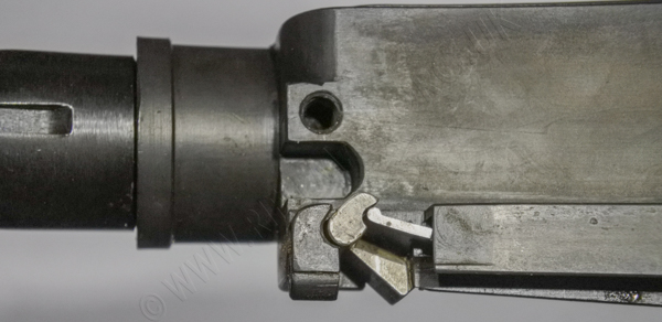
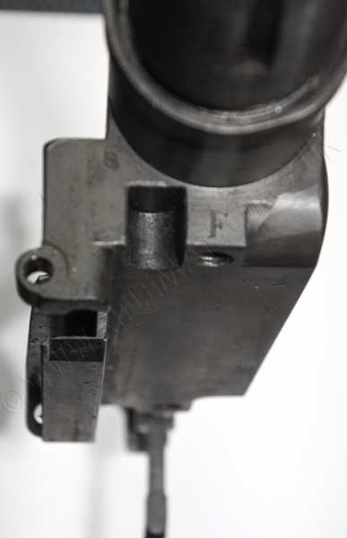
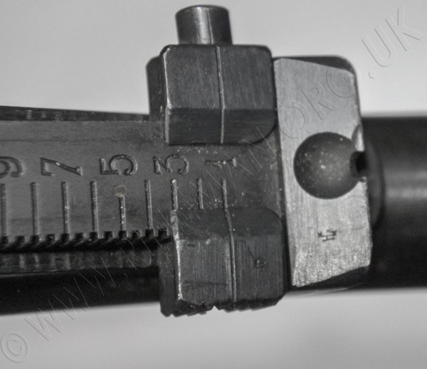
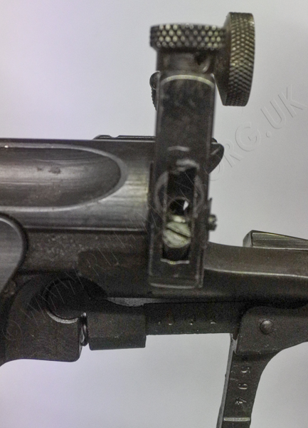
CLOSE-UP IMAGERY OF RIFLE
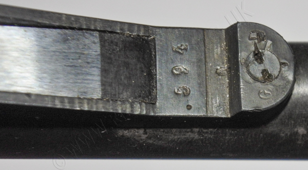
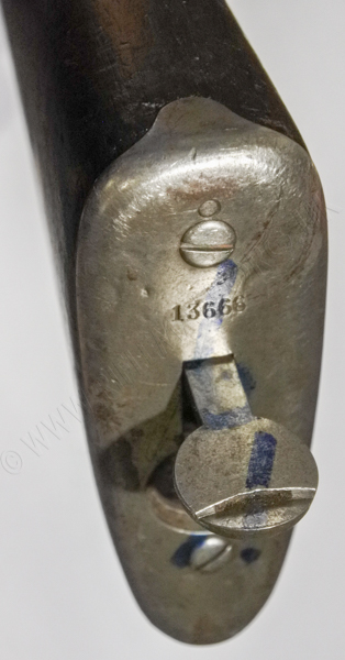
First, the receiver, showing the rimfire chamber
offset to twelve-o'clock.

The bolt is unchanged from the full-bore service rifle,
as the rimfire cartridge is loaded into a chamber eccentrically offset in the breech by approx. 3mm.
 .....
.....
As is evident from the still present centre-fire firing-pin.

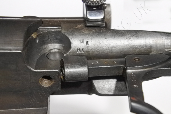
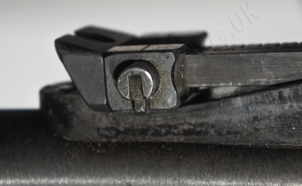
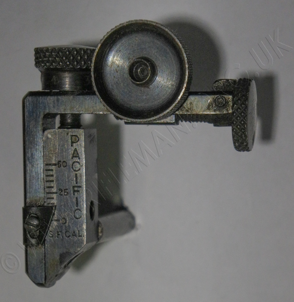
The cut-off lever and spindle that is replaced
by any of the "No gunsmithing" rear aperture target sights.

The following translated information is sourced from www.kvf.no
MODEL & PRODUCTION
Type: ......................... Rifle
Manufacturer: .............Kongsberg Arms Factory
Constructor: ................Ole Herman Johannes Krag and Erik Jørgensen
Customer: ...................Armed forces
Model: ........................M/1894 Krag (rebuilt)
Calibre:...................... .22 LR
Production period:....... Late 1950s
Quantity produced: ...... 3000
Serial number: ............. Various
TECHNICAL DATA
Mechanism: ................... Bolt
Wood: ............................ Walnut/beech or birch
Aim: ............................... Arch flap, open 100-2200 m
Equipment: ...................... Screwdriver, Oil bottle
Description: the Kongsberg Våpenfabrikk factory received Norwegian patent no. 46138 for a .22 barrel on February 18, 1929. The rifle was modified from the Krag Jørgensen M/1894 but the new barrel had an eccentric chamber and leed. This made it possible to replace the original 6.5 mm barrel with a small-bore rimfire one. The only change otherwise necessary was to shorten the striker somewhat, as well as make a minor modification to the existing extractor.
The rifles were produced from the late 20s, and were sold individually and in batches to private owners and shooting teams. It was possible to send rifles to KV for barrel replacement. The rifles were refurbished and received new surface treatment with immersion in browning baths. The inside of the action was not closed. The original sight was adapted to the barrels so that they could be set to approx. 500 m to get the correct point of impact at 15 m. The individual weapon was usually stamped on the right-hand side of the base with the distance at which the sight had to be set, e.g. 480 M. The original bases were retained.
The weapons that were converted were taken from the Army and Navy series. Both Kongsberg and Steyr weapons were used. The parts were often mixed from several different rifles. The weapons were distributed to the Army and Home Guard units for indoor shooting and were in use until the late 1980s. The rifles were then withdrawn due to wear and tear in the extractor groove. This could lead to a gas escape. During the period when the armed forces used the weapons, some had undergone more or less official changes such as diopter sight. In 1989, the weapons were disposed of. These were sold to the Voluntary Shooting Service, collectors, or given to the Defense Museum. Some of the weapons were also destroyed. The weapons are relatively common to this day.
Source for the above data: Norwegian Military Rifles after 1867, Karl Egil Hanevik, ISBN 82-993143-1-3, page: 167-168
The 1904 edition of the British War Department's "Text Book of Small Arms"issued by Her Majesty's Stationery Office (of Queen Victoria) included a section on the U.S. Krag that is copied below.
This gives a highly detailed description of the rifle's components and operation.
The two drawings to which the text's indices refer are illustrated first.
Hover over or Click image to bring up hi-res file and magnifier
Hover over or Click image to bring up hi-res file and magnifier
THE TEXT
UNITED STATES.
Krag Jörgensen, 7.62 mm., .3-inch, Pattern 1898.
Barrel
The barrel has no reinforce over the chamber, but tapers from a point 2 inches in front of the body to the muzzle.
Foresight
The foresight is a narrow plate which is pinned in a longi-
tudinal groove in the foresight block. The backsight bed is soldered and screwed to the barrel. The leaf is pivoted near its rear end, and is controlled by a flat spring screwed to the front part of the bed. The sides of the bed are formed into curved ramps which give elevations from 200 to 600 yards with the leaf down. The 100-yard graduations are marked and numbered on the left side of the bed and 25-yard graduations are shown by lines on the right side. The leaf is provided with a solid cap and with a slide which is clamped at any desired elevation by means of a screw with a milled head on its right side.
The end of the screw bears against the right edge of the leaf.
The slide is taken off by detaching a plate from its face. The right end of this plate fits into an undercut seating in the slide; the left end is secured to it by a screw. In a recess within the slide is a spiral spring, the two ends of which bear against the inner faces of the leaf. This prevents the slide from falling down of its own weight when the clamping screw is loosened. The leaf is graduated from 700 to 1,800 yards; the slide and cap are provided with small semi-circular notches for aiming.*
* A windgauge sight has been recently adopted for this rifle. The back- sight bed is divided horizontally into two parts; the bottom part is fixed to the barrel, the top part pivots on a vertical screw passing through it, into the lower part, about 3/4-inch from its front end. The rear end of the upper bed is circular, with the pivot screw as centre, it is held down by a rib projecting from its rear end, which works in a corresponding groove in the lower bod. A scale is marked on the rear end, and opposite each end of the scale are zero lines on the lower bed. The upper bed is clamped in any desired position by means of a nut with tliumbpiece, which bears on the front end of the bed. This clamping nut works on a vertical screw, projecting from the lower bed, through a curved slot in the upper bed.
There are two V's on the slide, one for use leaf down, from 1 to 400 yards, the other for use leaf up, from 500 to 1,900 yards ; when aim is taken over the top of the leaf, 2,000 yards elevation can be obtained. A small hole is drilled through the slide below the V, forming an aperture sight, when the leaf is up, it can be used with the graduations marked on the face of the leaf from 100 to 1,800 yards, and is very useful for deliberate shooting.
Fig. 8.
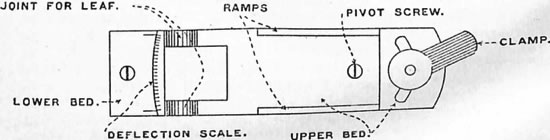
Backsight bed of windgauge sight of U.S.A. Krag Jörgensen rifle.
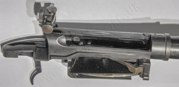
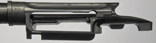
Body
The body screws onto the breech end of the barrel in the usual manner, and is cut away on the right side of the bolt way to facilitate ejection and single loading. Below the bolt way is a separate horizontal chamber (1), forming the magazine, which communicates with the bolt way by means of an opening (2) on the left. The left side of the magazine is closed by a plate which is secured to the body by a screw. The opening into the magazine on the right is closed by a cover, M, to be described later on. The seating (3) for the single lug on the bolt is below and immediately in rear of the entrance to the chamber. The lug enters it by means of a cam-shaped groove on the right. A recess (4) is cut in the body above the entrance to the chamber for the end of the extractor. The rear part of the body does not form a complete circle, but is slotted through on top to afford a passage for the extractor and the lug on the bolt. The rear end of the body forms a tang, which has a longitudinal groove (5) for the cocking piece stud and a recess (6) for the bolt lever to turn down into.
In the left side of the body a longitudinal hole is bored from the rear end into the exit from the magazine for the stem of the cut-off, L. In the bottom of the rear part of the bolt way is a slot (7) for the ejector.
Bolt
The face of the bolt cylinder, A, is recessed for the base of the cartridge, which has a rim. There is no separate bolt-head.
A single locking lug (8) is situated at the head of the bolt. On the right side, when the bolt is closed, is a solid rib (9) which, in the closed position, bears against a shoulder (10) of the body, and assists in taking the recoil. The lever (11), terminating in a knob (12), is at the rear end of and at right angles to the bolt cylinder. The lever is partly cut away on the right side to clear the body.
A cam-shaped recess (13) is cut in the back of the bolt, and close to it is a small groove (14) for the point (21) of the cocking stud to rest in when the breech is open. A gas escape hole is bored into the striker way at (15). A flange (16) runs partly round the rear end of the bolt and serves to retain the bolt plug, F.
A recess (17) is cut in the back of this flange for the end of the safety bolt, H. A groove (18) is cut in the bolt for the ejector, I, to work in.
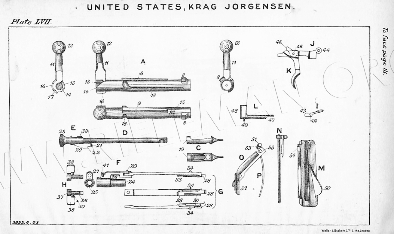
Mainspring
The bolt is bored out from the rear for the mainspring, which is of .05-inch wire, with 39 coils set to a length of 5.25 inches.
Striker
The striker is in two pieces; the point, C, forms the front end of a hollow cylinder which fits over the other portion, UT and is secured to it by a knuckle joint. The mainspring bears against the rear end (19) of the cylinder, C.
Cocking piece
The rear portion of the striker, D, screws into the cocking niece E from which the cocking stud (20) projects downwards, travelling in the groove (5) cut for it in the tang of the body. The front part (21) of the stud (20) is shaped to fit into the cam recess (13) of the bolt. The stud has only a full bent (22). The cocking piece has a roughened button (23) for catching hold of.
Bolt Plug
The" striker passes through a plug, F, which fits into the rear portion of the bolt, and against which the mainspring bears at (24) The plug is bored out from the rear for the cocking piece, and has a slot (25) in it underneath for the cocking stud to travel in. On top it extends over the bolt, travelling in the slot cut in the body cylinder. A groove (26) is cut in this portion of the plug, in which a corresponding flange (16) on the rear of the bolt works, and prevents the pressure of the mainspring at (24) from forcing the plug to the rear. This top part is bored out from the rear at (27) for the safety bolt H.
Extractor
The extractor, G, which is a long flat spring terminating in the usual claw (28), is pivoted by a pin (29) to the bolt-plug and fits over the bolt rib when the bolt lever is raised. It has a secondary spring (30) mortised into it which fits under the projection (31) in the body, which prevents it rising during the primary extraction. The extractor claw projects over the face of the bolt-head recess. When the bolt is closed, the end of the extractor fits into the recess (4) in the body, but when the bolt lever is raised, the projection (32) on the front of the rib of the bolt bears against the projection (33) on the extractor and guides it when the bolt is being drawn back, as does also the slot in the cylindrical portion of the body. The pin (34) on the extractor engages in the recess (35) in the body, and holds the bolt steady when it is drawn back.
Safety bolt
The stem (36) of the safety bolt, H, fits into the cylindrical hole (27) of the bolt plug. On the left side of the safety bolt the front end of the stem (36) is half cut away and the head is recessed at (37). When the finger piece piece (38) is turned to the left the flange (16) on the bolt is free to pass under the stem of the safety-bolt, and the cocking piece can pass through the groove (37), but when the finger piece is turned to the right the end of the stem (36) enters the recess (17) in the flange of the bolt, and the head of the safety bolt prevents the passage of the projection, (39) on the cocking piece. The bolt cannot then be opened or the rifle fired. The safety bolt is secured to the bolt sleeve by the stud (40) which is operated by a spiral spring, and works in the groove (41) in the bolt plug.
Retaining arrangement
There is no retaining bolt, but the lug (8) on thebolt,
coming up against the resisting shoulder (10) stops the backward movement of the bolt. To remove the bolt it must be drawn back; the extractor must be lifted so as to clear the top of the body and the bolt lever turned to the left; this brings the lug opposite the slot on the body cylinder and the bolt can then be withdrawn.
Ejector
The ejector, I, fits in a slot at the bottom of the bolt way, a small pin passing through it at (42); the rear end (43) projects upwards into the groove (IS) in the bolt. O11 drawing back the bolt the front end of the groove (18) strikes the projection (43) and depresses it. This raises the front end of the ejector, which smartly strikes the underneath part of the cartridge and tosses it out of the rifle.
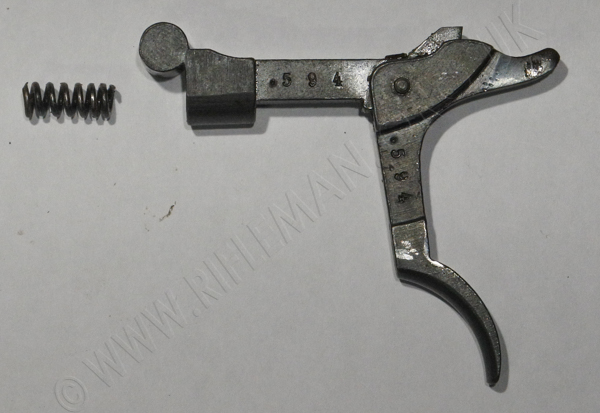
Sear
The sear, J, is pivoted underneath the body by means of a, knuckle joint (44). Its bent (45) projects into the groove (5) in the tang of the body and is pressed upwards by a small spiral spring fitting in a recess underneath the knuckle joint (44).
Trigger
The trigger, K, is a bent lever with a recess on its upper surface in which the end of tho sear works. It is pivoted to the sear by the pin (46). It has two projections 011 its upper surface, which bear in succession against the underside of the tang and produce the double pull-off fully described in the Austrian Mannlicher.
Action of the bolt
The bolt mechanism acts in an exactly similar manner to that already described in the Danish Krag Jörgensen, except that the ejector throws out the cartridge as above described, instead of striking the base of the cartridge.
Cut-off
The cut-off, L, has a stem which works in a hole bored in the left side of the body parallel to the bolt. Its front end enters the opening (2) leading from the magazine into the bolt way, and is partly cut away at (47). Whan the finger piece (48) of the cut-off is vertical, the clearance (47) allows the head of the cartridge to pass, and be pushed forward by the bolt, but when the finger piece is turned down the solid end of the stem keeps the head of the top cartridge out of the bolt way, so that the cartridges are not fed into the chamber on working the bolt. A small pin (49), operated by a spiral spring, projects from the underside of the finger piece and works in a small groove cut for it; this prevents the cut-off from working out of its seating.
Magazine
The magazine is a horizontal chamber underneath the bolt way. It communicates with the latter by an opening (2) on the left of the bolt way. The left side of the magazine is closed by a plate, the front end of which engages in a recess of the body, and the rear end is secured by a screw.
The entrance to the magazine is on the right side of the body. It is closed by a cover, M, which is pivoted on a horizontal pin, N, this latter being seated in a hole parallel with the bolt below the entrance to the magazine. A tall rib (50) on top of the cover serves as a thumb piece for opening and shutting the cover. The platform, O, consists of a bell crank lever. It is pivoted on a vertical pin (51) at the end of its shorter arm. The pin (51) is pivoted in the body at the front end of the entrance to the magazine. An extension piece (52) is pivoted on the end of the platform to assist in guiding the cartridges. The magazine spring, P, consists of a flat curved spring which lies in a recess under the opening to the magazine. One end of it presses on a tooth (53) on the bottom of the axis of the platform and tends to keep the plat form pressed into the magazine chamber. On opening the magazine cover, a tooth (54) on its hinge engages in the bend of the platform (55), and draws it back until it lies completely within the cover. Five cartridges can then be freely dropped into the magazine. On shutting the cover the tooth (54) is disengaged from the bend of the platform, which is then forced forward by the magazine spring, pushing the cartridges forward and upwards till the top one reaches the opening into the bolt way. This opening is too small in rear to allow the cartridge head to completely pass through, but when the bolt is pushed forward its face catches the rim of the cartridge and moves it forward, the bullet being guided into the chamber along an incline in the left side of the body until the base comes to the enlarged portion of the opening (2), when the whole cartridge clears the magazine and is forced into the chamber by the bolt. The magazine can be charged with the bolt either open or closed, and can be replenished when partly empty with one or more cartridges.
Stock.
The stock is in one piece without pistol grip, but with fore-end grooves for the fingers and thumb of the left hand. The stock and body are secured together by two screws passing up from underneath, through the ends of the trigger guard, into the rear end of the magazine, and into the end of the tang. The trigger guard (56) is a separate component of ordinary pattern. There is a handguard extending from the rear end of the barrel to the lower band. It is secured to the barrel by two Ω springs riveted to it and which partly encircle the barrel. The backsight bed passes up through an opening in the centre of the handguard.
Bands and swivels
The upper band is secured to the fore-end by a screw passing through it. It is longer than usual, and has a strap at either end passing over the barrel. On its underside in front there is the usual sword bar, and in rear a piling swivel similar to that on the Lee-Enfield rifle. The lower band is split at the bottom, the ends being drawn together by a screw, on which is pivoted the sling swivel. The other sling swivel passes through a boss on a plate which is screwed to the underside of the butt. No cleaning rod is carried in the rifle.
Sword bayonet
The sword bayonet has a blade about a foot long, sharpened on one side for its whole length; on the other side for 4 inches from the point.
The crossbar, grips and pommel are similar to those of the bayonet used with the Lee-Enfield rifle. All the steel work is left bright.
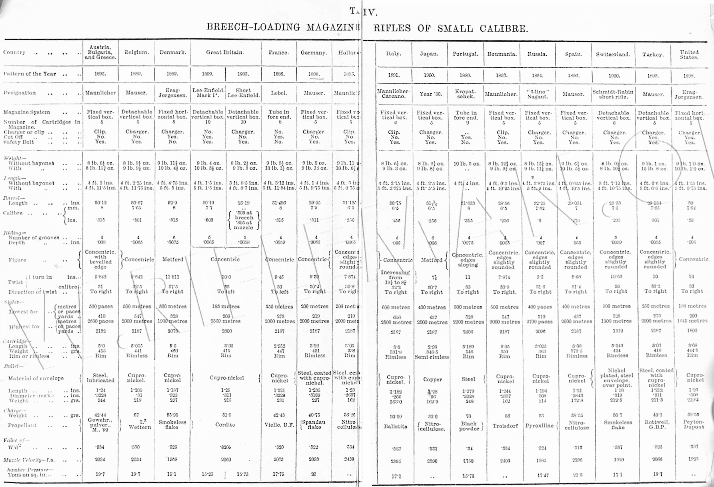
For weights and dimensions see Table IV, Appendix.
________________
Remainder of page still under construction as at August 2025
(Awaiting image captions, etc.)
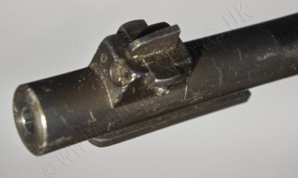
The fore-sight is in a lateral dovetail in the mounting block,
and is windage adjustable with a cross-screw, and locked into position by a screw in the front of the mount.
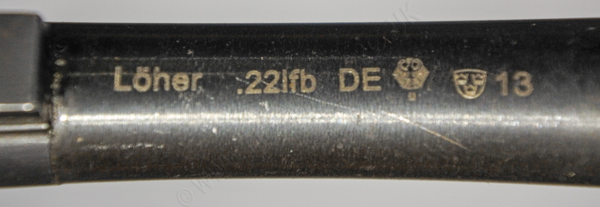
The barrel was manufactured by Löher in Germany. The company remains extant, but now manufactures only machine tools.
___________________
Weights and Dimensions, Table IV, from Appendix of Text Book of Small Arms 1904
Return to: TOP of PAGE
See this website's Raison d'être